The AAduino Zero

When I released the AAduino (original post here) last year I did not really expect the coverage it rendered. Even my WordPress server was surprised as referrals from Hacker News and others brought it to its knees. Building on the ATMega 328 was a natural choice at the time but I really wanted to move to 32 bit ARM micros. One of the reasons is the great debug support available using the impressive Black Magic Probe or cheap ST-Link clones. Gone are the days of my youth when an ARM JTAG debugger would set you back €2000.

Crowd Sourcing the AAduino Zero

So here we are today, the AAduino has evolved into the AAduino Zero that will start crowd sourcing over at Crowd Supply soon. Sign up today and get notified when the campaign kicks off!

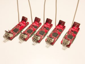
I have previously written “soonish” about the start of the campaign but now I can say “soon” with confidence 😉 I have a few hand built prototypes that are working as expected and will go into production with no design changes. I have a quotation from Seeed Studio and the campaign will launch as soon as the final details have been decided upon (pricing being one of them).

Specs

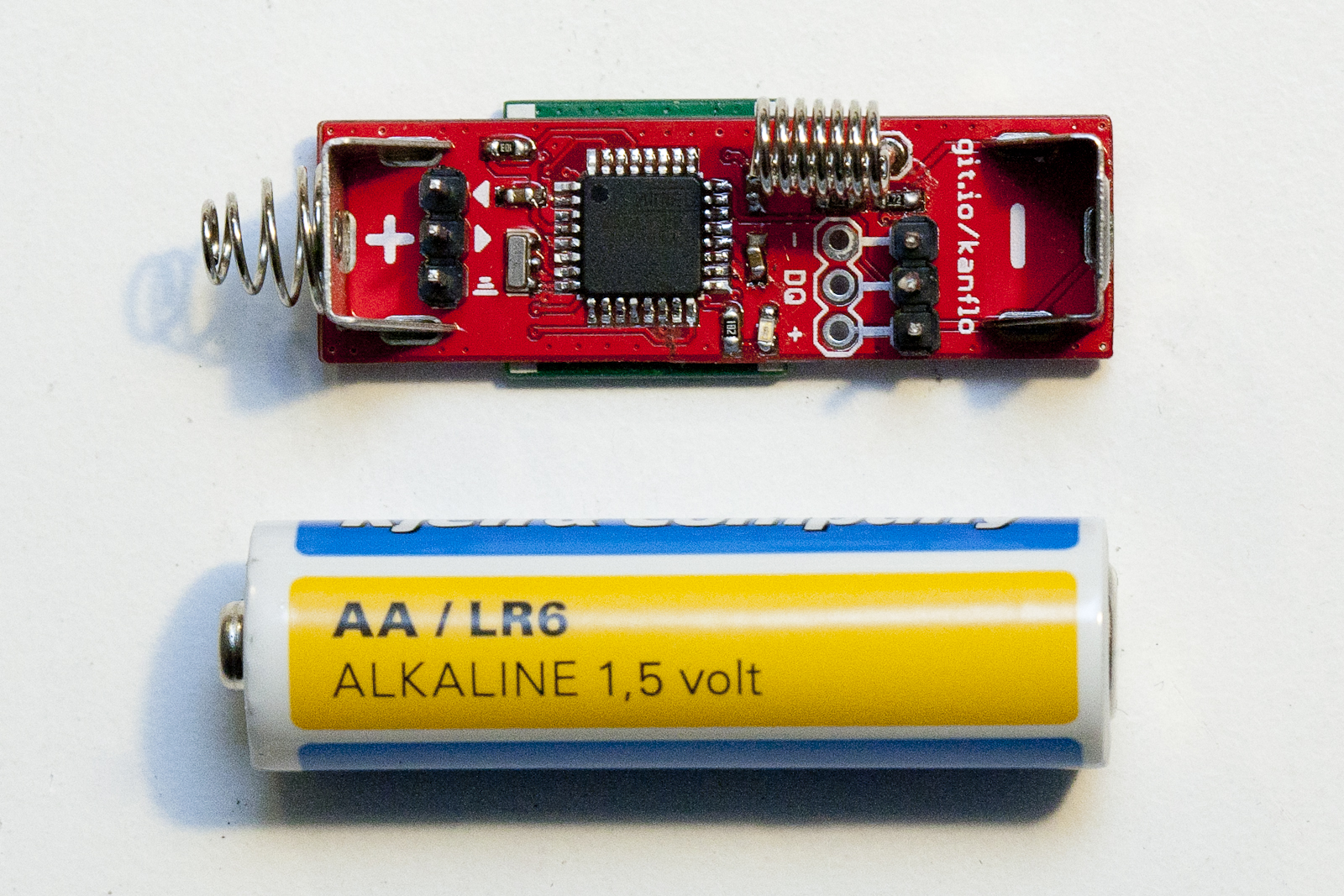
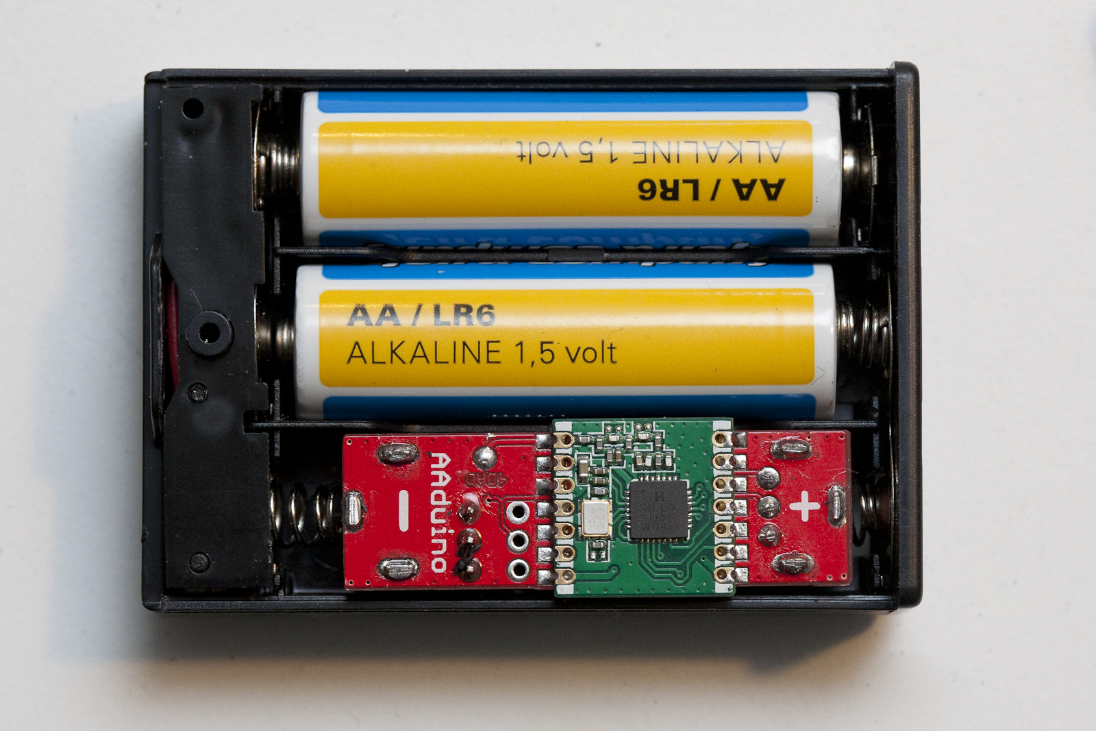
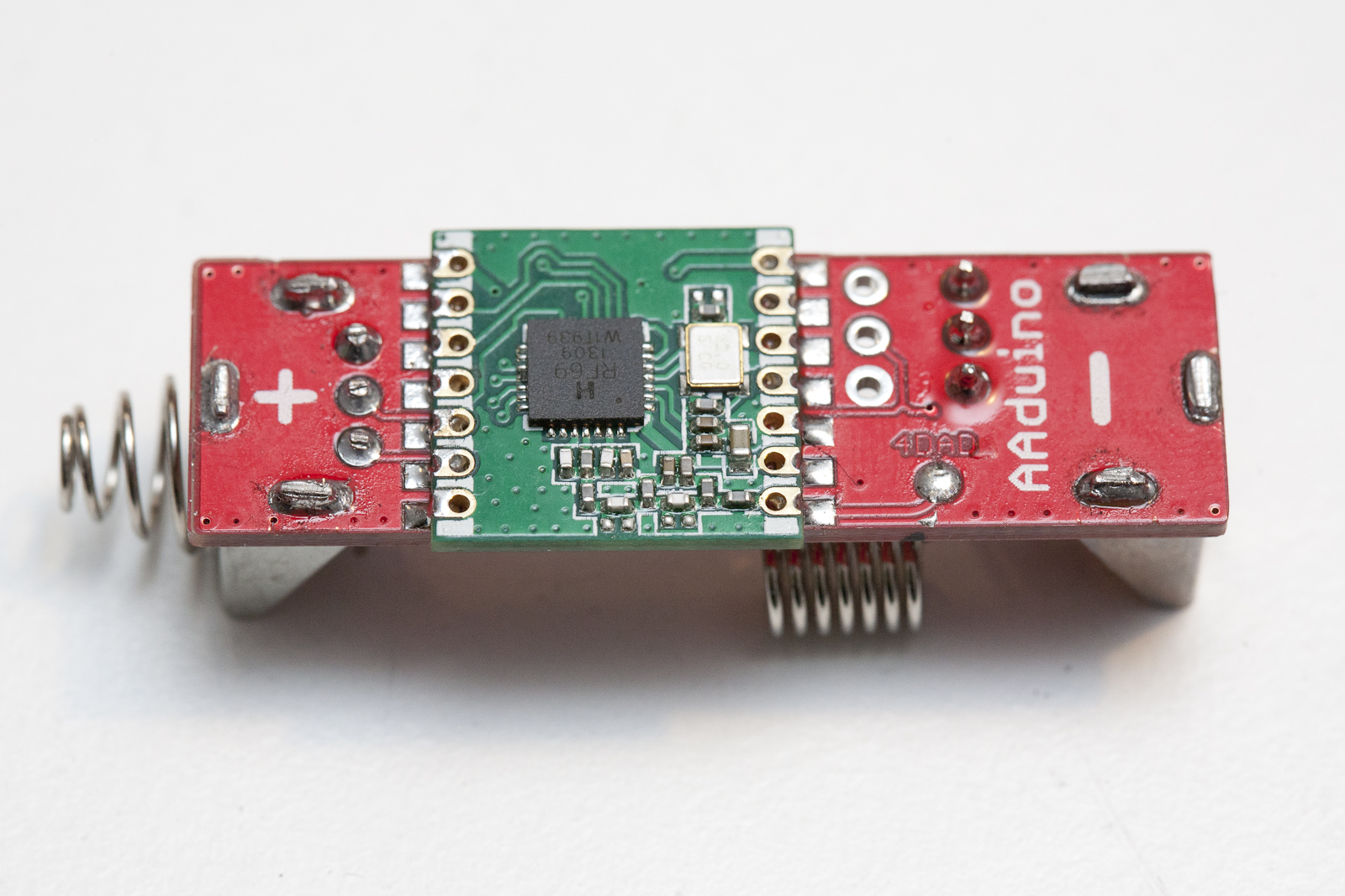
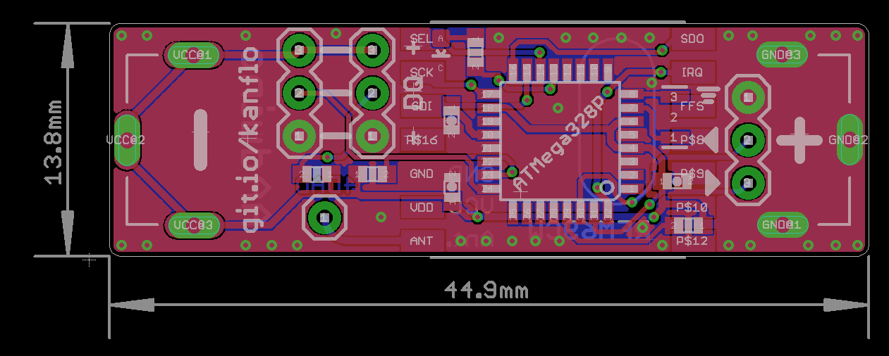
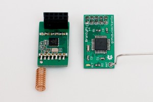
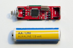
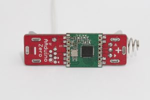
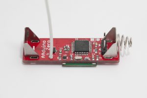
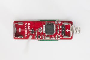
The form factor is identical to the original AAduino, as is the RFM69CW companion, but the rest has changed. The micro is now an STM32L052, the temperature sensor is a TMP102, there is polarity protection and also a serial flash which will enable wireless firmware upgrades or data logging applications. A 32kHz oscillator drives the real time clock of the STM32 and for extendability there is a 1 pin IO port (yes, one pin only). The UART (for flashing and debug output) sits on a convenient 0.1” header as on the original AAduino and there are test points for power, SWD and UART.

Here are the full specs:

  • STM32L052 micro controller with 32kb flash, 8kb RAM, 2kB EEPROM
  • RFM68CW radio module
  • TMP102 temperature sensor
  • 4Mbit serial flash for sensor data logging and wireless firmware upgrades
  • 32kHz oscillator for RTC
  • Activity LED
  • Reverse polarity protection (the original AAduino had none)
  • 1x digital/analog I/O port
  • UART port on 0.1” header
  • Pre-programmed with serial boot loader
  • Minimum supply voltage: 1.8V
  • Maximum supply voltage: 3.6V
  • Minimum power consumption: 8μA. Yes, eight microamps

Software & demos

Now that the hardware design is frozen I am working on the software including some demos. The AAduino Zero is currently programmed in C using the lovely libopencm3 project. I am planning on adding Arduino IDE support as not everyone are comfortable with installing toolchains, running makefiles and so on.

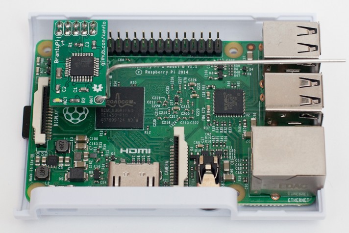
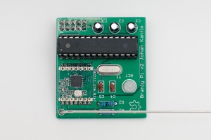
The first, and most obvious demo, is to get one AAduino Zero talking wirelessly to another one acting as a gateway, forwarding the received packets to eg. a Raspberry Pi. We will see about the next demo implemented but it might be an energy monitor as the one I was using broke down recently 😉

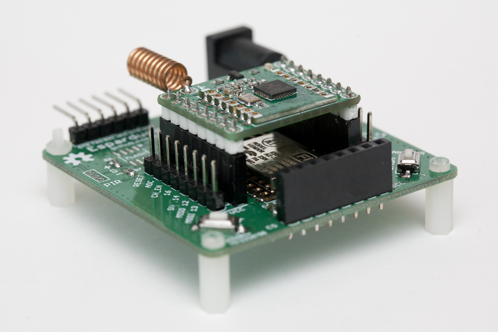
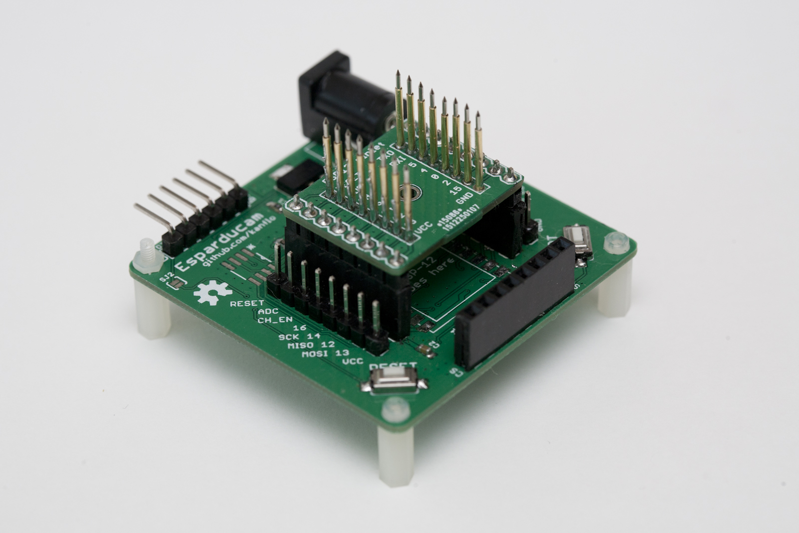
A tiny test fixture companion

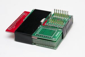
In addition to the AAduino Zero, I designed a small test jig to go with it. While the jig is useful for SWD flashing and debugging, it is not required for application development; the AAduino Zero will have an “Arduino style” serial boot loader. I designed three parts in Fusion 360 to hold the AAduino Zero in place:

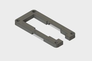
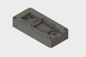
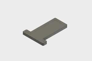
The “holder” is placed on top of the “jig” and both are fastened to the PCB using M3 bolts. The AAduino Zero goes into the holder and is locked in place with the small “key”.

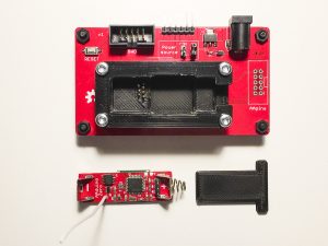
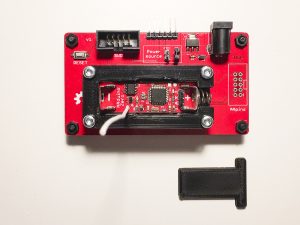
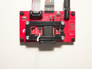
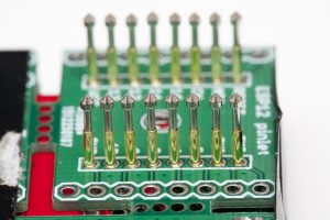
Pogo pins connect the device to the SWD and FTDI ports on the back and provide power from the DC jack. The unpopulated “AApins” connector is meant for a small hand held pogo pin programming adapter currently in production. It has not been decided if the jig will be included in the campaign but as mentioned previously, it is not required for working with the AAduino Zero.

Open Source?

As always, very much so. Both hardware and software will be published on on GitHub, with one small caveat. The Eagle design files will only be published once the campaign is over and the AAduino Zeros start reaching the backers.

Bridging ISM radio and wifi for lunch money

The ESP8266 has taken the maker community by storm and the hype is well deserved. Before the ESP we had the HopeRF ISM radio RFM12 and its successor RFM69. So is the ESP8266 an RFM69 killer? I would say no. Hell no even 🙂 The RFM69 is still very well suited for certain applications and the ESP8266 will not run for 2+ years on a set of AA batteries. The two can however play nicely together as a low cost ISM/wifi bridge. I did a custom PCB for this in the shape of a somewhat large USB stick, dubbed “Espism”.


Currently it works as an ISM sniffer posting the received packets on the MQTT topic espism-<macaddr>. Packets are posted in hex followed by the RSSI value:

espism-5ccf7f147cd Hello from 172.16.3.120
espism-5ccf7f147cd 016340630001000000c375b642[-27]
espism-5ccf7f147cd 630180[-57]

A set of four LEDs indicate received packets. Well three LEDs as I made a mistake on the ground plane. The MQTT server IP and RFM69 network information is hard coded into the binary.

I ported Andreas Heßling’s STM32 RFM driver to the lovely ESP Open RTOS, my swiss army knife for ESP8266 development. The type-A right angle 90 degreee USB connector and 3x6x2.5mm push button can be found for little money on eBay. The push button currently serves no purpose but the plan is to perform a “master reset” of the device using this button. The rest of the BOM consists of 0603 resistors and capacitors, an LM1117 3.3V regulator and a SOT23 P-mosfet for driving the 0603 LEDs. Oh, and the ESP12F talking to an RFM69CW. The BOM should add up to about the price of lunch.

Code and schematics on Github as always.

The AAduino


More news: read all about the new AAduino Zero.

News: the crowd sourcing campaign for  the AAduino will start soon, sign up at CrowdSupply to be notified! The specs have been beefed with an STM32L0 cpu and the temperature sensor is now an industrial grade TMP102.

Update: you can now order the AAduino PCB from DirtyPCBs.com and get a Commadorable 64 bonus PCB for free.

I have been using Nathan Chantrell’s Tiny328 for quite some time as my swiss army knife ISM radio node. Now I wanted a more slim ISM node as my setup with a Tiny328 on a breadboard is not very “deployable”. I could of course 3D print a case for the Tiny328 but I have limited access to 3D printers and do not feel I have the time to explore that exciting part of the maker world just yet. This leaves me with finding off the shelf project boxes with a compartment for 2x AA batteries and the “radioduino” (and in an acceptable form factor). That search came up disappointingly, and surprisingly, short. I did have a set of standard eBay AA battery holders and looking at the 3x variant it occured to me. I needed to shrink the radio node, and the AAduino was born.

Honey, I shrunk the radioduino!

The AAduino is an wireless Arduino clone the size of an AA battery with Keystone battery terminals rotated 180° to act as positive and negative terminals. It is powered by an ATMega328p and is fitted with an RFM69C companion. There is room for two DS18B20 temperature sensors and an indicator LED.

I still think it looks a bit weird :)
I still think it looks a bit weird 🙂

It runs at 8Mhz to allow for greater life span since the CPU can run at a lower voltage. I have fused the 328 to brown out at 1.7V which is a bit out of spec at 8Mhz and slightly below what the RFM69C needs. Running at 4Mhz would be more suitable but I will see how well the node performs when the batteries are draining out.

AAduino, RFM69C side

Since the RFM69C is somewhat wider than an AA battery I used a file to make it slightly narrower. There is some room for that kind of modification without damaging the module. Update, the RFM69C will fit without modification. Next I clipped the legs of the DS18B20 until about 5mm remained and soldered it to the 3x pin header on the AAduino. I then drilled a hole in the battery box where the sensor can protrude and a small hole for the LED to shine through. The wire out of the battery box was cut, shorted and stuffed away inside the box.

AAduino inside 3xAA box

I use battery terminals from Keystone available from RS Components, positive and negative. There seems to be a cheap eBay alternative but I have not tested those. The + and – markings on the PCB indicates (this is important, read carefully) the positive and negative poles of the battery we are pretending the AAduino is. The Keystone spring contact should be soldered to the + marking and the button contact to the – marking. There is no protection diode here so be careful. Also note! If you want to power the AAduino from a bench power supply, connect the power supply’s black negative lead to the + marking and the red positive lead to the – marking.

aaduino-v2

The 3xAA boxes are also from eBay and there seem to be two different types. One that is really good and one that is really crappy. I will let you in on the secret of buying the correct one. The good ones have a nice build quality and plastics and look like this. Note the rectangular piece of plastic below the battery compartment extending from side to side.

Good 3xAA holder
Good 3xAA holder

Looking at the crappy ones, well you can tell can’t you? In the top left corner it seems someone used a soldering iron on the poor thing. The lid does not snap in place very well and the plastics is really cheap.

Crappy 3xAA holder
Crappy 3xAA holder

Code, schematics and BOM on Github, as always.

A versatile ESP8266 development board

This is followup to my post about building a low cost wifi camera. I mentioned that the Esparducam board is well suited for ESP8266 development in general and here is why. In addition to the Esparducam board I also designed a number of addon boards. The boards are very small (21×26 mm) meaning you can fit two of them into a standard 50×50 mm PCB you can get produced for very little money. If you want to try a new component or connector and perhaps a newly designed footprint, make a “boardlet” and try it on the Esparducam.

The RFM69C breakout
The RFM69C breakout board

The “ISM boardlet” mounts an RFM96C for building a low cost ISM to Wifi gateway. The board has an optional LED (driven by a mosfet) for link indication. I ported André Heßling’s RFM69-STM32 driver for this board and even though I have not had the time to test that much, basic transmission works.

The ESP Pinlet
The ESP Pinlet

The next board, the esp-pinlet, serves as a test bench for ESP12 family modules. After soldering an ESP12e module to an Esparducam board I noticed it would not connect to my Wifi network. For the price of ESP8266 modules, I cannot complain about broken modules but I want to make sure the modules I mount on my boards actually work before soldering. So how do we test ESP12 modules without soldering? Pogo pins! The pinlet board has 1.02mm (40 mil) holes for pogo pins that allows for an ESP12 module to be firmly pressed against the pins while flashed and tested. You can find these on eBay.

Look ma, no solder!
Look ma, no solder!

Schematics on Github.

Update on April 27th

Th pogo pins I used initially where not that good as the needle like shape made them get stuck in some of the ESP12 modules. A much better alternative is the P75-E2 [eBay] type of pin (still 1.02mm / 40mil):

P75-E2 pins
P75-E2 pins

If you plan on building a pinlet board, make use of the fact that you get ~10 in each order to help with alignment.

Pin alignment
Pin alignment

The stack here (top to bottom) is the board having the pins mounted, a spacer board (the red one), five pinlet boards for alignment and at the bottom one board flipped upside down to keep the pins from sliding downwards. The package is fixed with tape and ready for solder.

Serializing data from IoT nodes

This is a followup to my previous post about my home automation/IoT system. I introduced some of the hardware used to build sensors and now I will look at an architecture for sending data from sensor nodes to a receiver. First I will explain the initial attempt at sending data from nodes and why that was destined to fail. Next we will look at an architecture for data serialization and quick node prototyping.


Doomed for failure

The first attempt at sending data was quite simplistic with data structures being sent through the air. The base structure looked like this:

typedef struct {
 unsigned char type;
 unsigned char seq_no;
} branly_report_t;

From this struct, holding a message type and a sequence number, I defined others for different kinds of sensor data, eg. temperature:

typedef struct {
 branly_report_t br;
 int temp;
} temp_report_t;

sensor battery voltage:

typedef struct {
 branly_report_t br;
 unsigned char vcc;
} battery_report_t;

plant moisture:

typedef struct {
 branly_report_t br;
 int temperature;
 unsigned int moisture;
 unsigned char alarm;
} plant_report_t;

and so on. Whenever I thought of a new kind of node I would implement a data structure for the data being transmitted. The receiver would look at the sequence number to skip duplicate transmissions and, most importantly, the type field to know what kind of data was being sent.


This is a horrible way of doing things.


Each new node type being built would require a copy paste job on both the node side (copy a previous implementation and make changes) and one on the receiver side (again, copy previous implementation and make changes). The receiver would of course require knowledge of all different branly_report_t types.

An actual architecture

The solution? Data serialization. Taking a step back makes one realize that we have do not want system with nodes reporting temperature, other nodes reporting plant moisture and so on. We want a system with nodes transmitting data. There is quite a difference between the two you see. Frankly we do not even care what kind of data nodes transmit until we want to act on it or look at it. Discussing this problem with a colleague I came up with the following model of nodes and contacts.

  1. A node has an identification number and one or more contacts.
  2. Each contact has an index number, 0..N.
  3. A contact has a predefined type that everybody agrees on.
  4. A contact may define a fixed reporting interval.
  5. A contact is readable and possibly writable.
  6. A contact may be violated, eg. a battery contact is violated if the battery voltage drops below a defined limit.

Any transmission from the node would be a reduced to a message with an updated contact property (contact identification number, contact value and flags for violations). A writable contact (eg. an RGB light) would receive messages with the same kind of data. Lots and lots of contact types can be defined and adding more further down the road is not as much of a hassle as the copy-and-past jobs mentioned earlier. Even more important, a node can report any data we want it to. My garage node could report inside and outside temperatures as well as the light intensity level (needed to know if I forgot to turn off the lights at night) without me cooking up some strange data structure only implemented once in one single node.

An example node

Before diving into how this idea of data serialization is implemented, let us look at an example. The Arduino node sketch below uses the RFM69 ISM radio to send data and has two contacts; battery voltage (reported every 1h 30min) and temperature (reported every 15min).

// Contact value getters
long temperatureValue(bool setValue, long value);
long batteryValue(bool setValue, long value);

RFM69 radio;
BranlyNode node(&radio, HW_VERSION, SW_VERSION);
BranlyContact battery(1, kTypeVoltage, batteryValue, k1Hour+2*k15Minutes);
BranlyContact temperature(2, kTypeTemperature, temperatureValue, k15Minutes);

long batteryValue(bool setValue, long value)
{
 (void) setValue; (void) value; // Contact is not writeable
 return 2940; // Sample data
}

long temperatureValue(bool setValue, long value)
{
 (void) setValue; (void) value; // Contact is not writeable
 return 245; // Fixedpoint, 24.5deg (sample data)
}

void setup()
{
 radio.initialize(NODE_FREQ, NWK_ID, NODE_ID);
 radio.sleep();
 radio.encrypt(CRYPT_KEY);
 battery.setLowerThreshold(2400); // Contact violated if VCC drops below 2.4V
}

void loop()
{
 node.run();
}

Yup, it does not take more code than that to create the full node software stack. Define the node, its contacts with contact getters (and setters if contact is writeable), define reporting intervals and call node.run();

Nodes

A node has, besides its contacts, version fields for hardware and software and an internal state (refer to BranlyNode.cpp). Upon boot the node step though its mCurState state variable until it has synchronized with the receiver. It will go through the following steps, requiring an ACK from the receiver in each step:

  1. send a ping packet and wait for a response from the receiver.
  2. send a hello packet with HW/SW versions.
  3. send a complete list of its contacts.
  4. send a complete contact report.
  5. wait until the next reporting interval and send a report on that specific contact

The receiver requires no configuration in order to receive data from a node. Instead, the node will tell the receiver what kind of data it will transmit.

Contacts

A contact (see BranlyContact.cpp) has an index and type as mentioned as well as a getter function and optional reporting interval. Contacts may be “enqueued” meaning its report will be transmitted on the next call to node.run. A button contact will typically be enqueued from an interrupt handler.

The radio protocol

The radio protocol has beed designed to be minimalistic to save power (critics may say the ping packet is not strictly necessary) and the heavy lifting is done in BranlyProtocol.cpp.

Each contact in the contact list (see buildContactListPacket) occupies a single byte, 1 bit for writeable, 3 bits for index and 4 bits for type (currently limiting the number of contacts to 8 per node and contact types to 16 in all, probably needs to be increased).

In the contact report (see buildContactReportPacket), contacts are encoded in 2-5 bytes with a flag field (for tracking violations), a size field telling how many bytes are needed to encode the current contact value and the actual value (1-4 bytes).

Lastly, contact value reports (see buildContactValuePacket) also uses 2-5 bytes and are sent in the same manner as contact reports.

The receiver

The receiver reads frames tom the BranlyPi modem running this receiver sketch. On the host side, the receiver is written in python and posts the received data to an Emoncms installation. The beauty of it all is that the receiver can create the Emoncms feed for each contact for a node on the fly based on the contact list packet.


Closing remarks

The current architecture has really enabled me to quickly prototype new nodes without changing a single line of code in the receiver and very few lines of code are needed to create a new RF node. On the receiver side, names need to be added for nodes and contacts enabling automatic bridging between RF node updates and, say, MQTT. Martin Harizanov is working on something similar and it will be exciting to see what he has come up with. If you know other implementations on this topic, please let me know in the comments below.


Meet the Branly IoT platform

These days it seems everybody is tinkering with their own IoT project, I am no different.

It started almost two years ago when I, while looking to build RF nodes, stumbled across the blogs of Nathan ChantrellMartin HarizanovJean-Claude Wippler and Felix Rusu. These guys had built exactly what I was looking for and Nathan even offered the gerbers needed to order Tiny328 PCBs. Tiny328 is an Arduino based RF node fitted with the RFM69C ISM radio. My experience with soldering was limited and my experience with designing PCBs was none, I am a software guy after all. It turned out that reflow soldering PCBs with 0603 components in a hot plate is quite easy (and fun!) once you get the hang of it. Google is your friend.

My fist baby steps in designing PCBs was an Arduino based modem with the RFP69 radio and though hole components, the BranlyPi v2 (v1 was without an external oscillator which caused the ATMega’s buadrate to be off leaving the modem and the RaspberryPi unable to talk).

It was superseeded by the v4 (don’t ask about the v3) which was surface mounted components all the way. Schematics and gerbers are here if you want to build your own.

With all that hardware available it was time to write some software and make two Tiny328s talk. The “hello world” was LowPowerLab‘s “Struct send” and “Struct receive” examples. I soon attached a DS18B20 temperature probe to one of the nodes for some more fun (sic!) data. Software for the BranlyPi was written as well as a python script running on the RaspberryPi listening to the BranlyPi modem.

In all, I had the following setup:

  1. A node fills in data into a struct holding a type field. The types can be “temperature”, “battery voltage measurement” and so on. The struct is transmitted to the BranlyPi modem.
  2. The BranlyPi modem receives the struct and formats in into a textual representation that is sent to the RaspberryPi over UART, eg.
    T:node id:rssi value:temperature

    and

    B:node id:rssi value:battery voltage
  3. The gateway script on the RaspberryPi reads the line above from the UART and posts it to a local Emoncms installation.

The node was placed in my garage with the probe outside. I had (sort of) built my own RF thermometer. Cool! An identical node (with a different node id 🙂 was built and placed indoor. Next, how about building one of those moisture measuring plant nodes? Or one that could tell me if I had forgotten to turn off the lights in the garage at night? I had a feeling the RF network would grow.

So far all is well from a technical point of view. The current software architecture would however need a complete rewrite to be useful, more of that later. Source code and hardware docs on Github.

“Branly” you might ask? Édouard Branly was one of the early pioneers in wireless telegraphy.