Updated on September 2nd 2017.
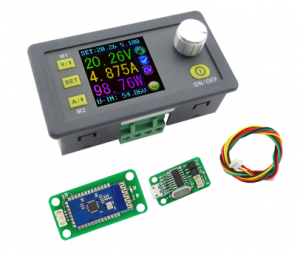
It’s exciting to see the continued development of the DPS5005 and ‘3005. Today Rd Tech released a version with USB/Bluetooth connectivity and I just ordered one to make sure OpenDPS runs on it. The new version seems be fitted with a JST has a JST GH connector which makes connecting an ESP8266 or a serial port a bit easier. It also has different MOSFETs by the looks of it.
Now I only need to wait 25-36 days for shipping. The wait is over and with a minor tweak (DAC needs to be disabled when turning off the output) OpenDPS is fully functional on the new DPS5005 “communication version”.
UART changes
There is no need to solder the UART anymore and you get a cable with the device. You can cut the cable in half to connect to your ESP8266 or FTDI-adapter but I recommend buying a set of cables and connectors from eBay. Search for “10SET JST GH Connector plug with Wires Cables” and get the JST-GH 4 pin kit. The pinout of the cable depends on what end you insert into your DPS (as both ends have female connectors). Thus, I will not say “red is VCC” as it will be “red is GND” if you connect the other end and observe the holy smoke. Look at the pinout below and determine which wire is which. The silkscreen is “V R T B” which I think should have been “V R T G“.
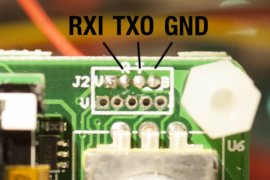
RXI indicates that this is the RX input (sic!) of the DPS5005. and TXO is the TX output (re-sic!) of the DPS5005. People have mixed up RX and TX for ages, calling your signals RXI and TXO will put an end to it. To the left of RXI is VCC which in the previous version could not power an ESP8266. I have not checked if the regulator has been changed to something more powerful in this version.
JTAG changes
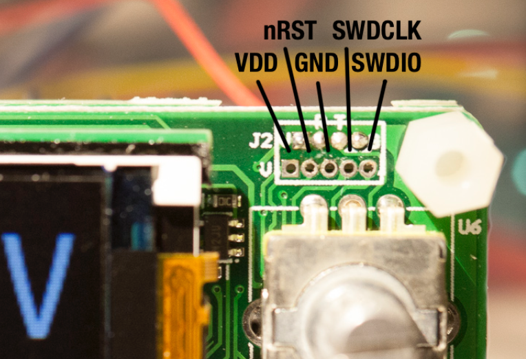
The JTAG connector on these new devices is called JST-GH and has a tiny 1.5mm 1.2mm, 1.25mm spacing and there is not room for running the JTAG wires toward the back of the device which makes a permanent JTAG solution cumbersome. When flashing, I simply pressed three test needle probes agains the GND, SWCLK and SWDIO connectors. Then again, most people will not need permanent JTAG but we all want a easy upgrade option for OpenDPS.
UART firmware upgrades
The solution is a bootloader that accepts firmware upgrades over UART. When unlocking your stock DPS, use whatever needles or pins you can find to connect GND, SWCLK and SWDIO and flash the bootloader. Then use dpsctl.py for the firmware upgrade:
% make -C opendps bin
% dpsctl.py -d /dev/ttyUSB0 -U opendps/opendps.bin
If you accidentally upgrade to a really b0rken version, the bootloader can be forced to enter upgrade mode if you keep the SEL button pressed while enabling power.
The display will be black during the entire upgrade operation. If it stays black, the bootloader might refuse or fail to start the OpenDPS application, or the application crashed. If you attempt the upgrade operation again, and upgrading begins, the bootloader is running but is refusing to boot your firmware. But why? Well, let’s find out. If you append the -v option to dpsctl.py you will get a dump of the UART traffic.
Communicating with /dev/ttyUSB0
TX  9 bytes 7e 09 04 00 27 86 0c b2 7f
RX 9 bytes 7e 89 00 04 00 03 66 0f 7f
The fourth byte from the end in the received data (0x03 in this example) will tell us why the bootloader refused to boot the firmware. See protocol.h for the different reasons.
Still not affiliated with Rd Tech. Would appreciate a discount though *cough* *cough* 😉