Adding a PowerWalker UPS to Home Assisstant

It’s been a while but as I have just stuggled with integrating a UPS into HASS, I thought I’d write a few words about it. If you like, you can skip the semi ranting paragraph below and jump to “And here we are”.

I have been hooked on Home Assistant for some time now and almost every single light in my house is smart connected. While that have lots and lots of advantages, there are a few disadvantages. Having software running in each light bulb means that light bulbs will crash (as in going off line, not as in getting shattered). Occasionally a light will not respond but after a quick reboot (sigh) it will be back on line. That reboot comes from me flicking the “old” light switches and the lights turning on after a mains power failure (a “feature”).

You might see where this is going. Twice this winter I have been rather rudely woken up at night when a power grid glitch caused a total of 3000 lux flooding my bedroom. I then need to rise from bed, manually turn off bunch of lights or await the HASS server reboot and turn the lights off from the comfort of my bed.

Of course it should not have to be this way. What if…lights at boot went back to the previous setting? Well, as the lights are radio connected, disturbances will happen from time to time and I am quite certain the software glitches too so the “lights on at power on” setting is needed. Crappy technology and buggy software that cannot be fixed need…work arounds.

And here we are

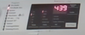
So I purchased a PowerWalker VI 600-3000 SCL to keep the HASS server alive during power grid glitches and blackouts. Integration was not straight forward. In case you want to do the same, here are my notes.

NUT add-on

First install the “NUT add-on”. Yes, add-on, not integration (that comes later). The “add-on” creates the server that the “integration” talks to. Go to “Settings > Add-ons” and search for Network UPS Tools or NUT. Next go to the NUT “Configuration” section. You need to define a user, UPS name and select a driver for your UPS. The driver for my UPS is called nutdrv_qx. While it enumerated as a USB HID device, selecting “HID” as driver at first threw me down the rabbit hole, wasting an entire evening of googling “NUT libusb permissions”. Pick nutdrv_qx and save time. Oh! And make sure to disable shutdown_host!

Now go back to the “Info” section and start the add-on. Checking the logs, the last line should be something like

   0.010152	[D1] Logged into UPS PowerWalker@localhost

I did experience the NUT service restarting every 10 seconds. It went away and I cannot explain what I did.

NUT integration

Go to “Settings > Devices & services”. Chances are the “NUT add-on” has been helpfully auto discovered. If so, dismiss it. Click “Add integration” and add the NUT integration. Specify a0d7b954-nut as host name and the user/password from the add-on configuration. Oddly, the auto discovered integration did not accept my credentials. Might have been a typo on my behalf. YMMW.

Next I need some UPS automation, but that is for another evening.

Final Notes

In case of a power outage, my UPS will beep every ten seconds which would probably be more of an impediment to a good night’s sleep than the 3000 lux blast I am trying to mitigate. Luckily it can be turned off, via another Linux box. Install the NUT toolkit with sudo apt install nut and run the command upsc PowerWalker@homeassistant.local. Enter the credentials from the NUT add-on (PowerWalker is the name given in the devices section of the add-on configuration).

Next check the settings using the command upsc PowerWalker@homeassistant.local. Somewhere you should see ups.beeper.status: enabled. Disable with the command upscmd PowerWalker@homeassistant.local beeper.toggle. It seems it takes a few seconds for the setting to persist.

If you have another UPS that I do, you can check the supported commands using the command upscmd -l PowerWalker@homeassistant.local.

Slava Ukraini!

Is the wash done?

Checking if the washing machine is done is a popular (not to mention useful) application. This is often done by sticking LDRs to the washing machine, adding IMU sensors or analyzing mains power usage or even the sound emitted.

I needed a solution with minimal time effort as I have lots of other things I want to do so I went with a Raspberry Pi Zero W and a PiCamera. Starting as “wash monitor” it transformed to “appliance monitor” as any appliance can be monitored. I have a single Raspberry Pi keeping an eye on both the washing machine and the tumble dryer.

The idea is simple, take a picture, process and count pixels:

  • All black: lights are off and the machine is off
  • Most black: lights are off and the machine is on
  • Few black: lights are on, machine state is unknown

Next, the “lights” and “machine” states are tracked and a notification is sent when “machine” goes from “on” to “off”. Pushover is used as notification service and MQTT for general service monitoring.

There are a few prerequisites that make this solution actually work (yes I know you objected to the idea):

  1. My washing machine is in the basement, ie. in a “controlled light environment”.
  2. The lights in the laundry room are Ikea Trådfri ones activated by a motion sensor and they switch off after a few minutes meaning we will never be stuck in the “lights are on, machine state unknown” state.
  3. Normally no-one enters the laundry room minimising the risk of false positives by a person dressed in black pants standing in front of the camera.

The system works great for me but might be completely useless to you 😀

MJPEG Streamer is used for snapping pictures and ImageMagick for processing. Pictures are cropped to only reveal the display which increases the percentage of non black pixels when the machine is on. Blurring is used to increase specular highlight of the LEDs, a threshold filter is applied making sure we end up with only black and white pixels (and no image sensor noise) and finally the histogram is calculated. The Pi is taped to the wall opposite the machines so it will not move (which would mess up the cropping).

Here is an unprocessed cropped picture of the washing machine display when the room is lit:

0% completely black pixels

(Applying blur and threshold filters now yields a completely white picture from which we can only determine the lights are on)

The same picture with the lights off:

Blur and threshold filters applied:

~84% completely black pixels

Lights off, machine off, blur and threshold filters applied:

100% completely black pixels

Installing and configuring

First clone this the Appliance Monitor repo:

git clone https://github.com/kanflo/appliancemon

You need ImageMagick, Python Requests and Paho MQTT and MJPG Streamer (and of course lots of stuff to be able to build):

sudo apt-get install imagemagick
sudo apt-get install python3-pip
sudo pip3 install paho-mqtt requests
sudo apt-get install build-essential git libjpeg8-dev imagemagick libv4l-dev cmake
git clone https://github.com/jacksonliam/mjpg-streamer.git
cd mjpg-streamer/mjpg-streamer-experimental
make && sudo make install

To spare the poor MicroSD card I use a RAM disk for image processing and a script is provided that adds the RAM disk to /etc/fstab:

sudo ./create-ramdisk.sh

Next, copy sampleconfig.yml and modify as needed (there are lots of comments to guide you). The “image processing parameters” section can be skipped for now.

A start script for MJPG Streamer is included where parameters such as white balance can be set:

sudo /home/pi/appliancemon/mjpg-streamer.sh start

If this fails, check the bcm2835 Video4Linux driver module is loaded and then try to start MJPG Streamer again:

sudo modprobe bcm2835-v4l2

To make it load on boot:

sudo echo "bcm2835-v4l2" >> /etc/modules

Snap a picture:

curl -so image.jpg "http://wash.local:8080/?action=snapshot.png"

Use this image to determine the crop area specified in ImageMagick style (blur and threshold are also IM style, check the ImageMagick documentation for help).

Now try the cropping and calculate the black level. The last two zeroes are “blur” and “threshold” (zero means disable).

./applimon.py -c washconfig.yml -t "290x120+20+410 0 0" ; open image-proc-washer.png
Black level: 0%

Now turn on the machine, turn off the lights and apply blur and threshold:

./applimon.py -c washconfig.yml -t "290x120+20+410 0x6 6"
Black level: 94%

And finally turn the machine off:

./applimon.py -c washconfig.yml -t "290x120+20+410 0x6 6"
Black level: 100%

You may need to elaborate with the blur and threshold parameters to get satisfactory black levels. I use the ones in the sample config for both my washing machine and tumble dryer.

Finally add the following lines to crontab -e:

@reboot /home/pi/appliancemon/mjpg-streamer.sh start
@reboot /home/pi/appliancemon/applimon.py -c /home/pi/washconfig.yml &
@reboot /home/pi/appliancemon/applimon.py -c /home/pi/dryerconfig.yml &

Code on GitHub as always.

The future of OpenDPS

Creating OpenDPS was a lot of fun and I am really enjoying seeing it in use on other peoples DPS:es. In this post I will elaborate on the future of OpenDPS, feel free to join the discussion in the comments below.

Architectural overhaul

The original OpenDPS firmware was “an application displaying a user interface allowing the user to set output voltage and current limit”. Over time the constant current mode was added due to popular demand 😉 Remote control is possible using dpsctl, a tool that “knows” what functions the OpenDPS firmware supports.

All that functionality still exists, but from a software architectural point of view the firmware today is completely different. With the recent UI overhaul, the firmware is “an application supporting functions and allowing the user to change parameters specific to these functions”. Sounds a bit dry, doesn’t it? The good news is that the “functions” implemented are CV and CC so the user will not notice things changed under the hood. Even better news is that it is now trivial to add new functions. The original CC mode was somewhat shoehorned into place while the rewritten one fit right into the software architecture. One new function I am thinking of is a signal generator.

Remote control

Remote control unfortunately is a bit broken at the moment. This is currently being fixed while performing some architectural changes to dpsctl too. My idea is that dpsctl should not have any knowledge about the functionality of the OpenDPS it controls. It will know about “functions”, “function parameters” and “activation/deactivation” of said functions. With this change there will be no need to maintain dpsctl when adding new functions to OpenDPS. Here is what it looks like right now on my local master:

% dpsctl -d 127.0.0.1 -F
Selected OpenDPS supports the cv and cc functions.

% dpsctl -d 127.0.0.1 -f cv
Changed function.

% dpsctl -d 127.0.0.1 -p v=3300 i=500

The commands above list the supported functions, selects constant voltage and sets output to 3.3V and current limit to 500mA. The OpenDPS will complain if the function does not exist or the parameters are incorrect.

Emulation

Did you notice the localhost IP address above? That was no typo, the OpenDPS firmware can now be run as a standalone application on your computer. This accelerates development of non hardware related application code and I am using it for the function and function parameter code right now. The emulator listens to UDP port 5005 and behaves just as an ESP8266 joined with a DPS. It additionally listens to UDP port 5006 where UI events can be injected:

% nc -u 127.0.0.1 5006
draw

This causes the emulator to draw an ascii version of the UI on its stdout (currently not that exciting)

0.00V
0.000A
0.0V

The parameter setting code is currently being worked on and I will push to GitHub it as fast as I can to restore remote control of OpenDPS. The function generator will arrive later this summer, its timeframe being weather dependent. Got any ideas for other functions? Let me know.

Disconnecting Sweden from Chinese e-commerce

As the saying goes: “it was fun while it lasted”. I always expected the shopping spree from AliExpress, eBay and friends in China would come to an end one day but did not expect it to go out with such a bang. Today PostNord (they handle snail mail in Sweden) announced they will impose a 125SEK + 25% VAT fee (about €16 in total) on every single parcel arriving from China. I would not mind paying VAT on China imports but I do mind getting robbed by the mail man. Apparently, there is an inflow if 150k Chinese parcels every day in Sweden. PostNord expects that number to drop to 120k/day. Multiplied with 125SEK/parcel, this will lead to “significant income” according to the PostNord spin doctor. I expect not.

Sources: BreakIt.seOmni.se (Swedish), The Local (English)

Easing the pain of SWD on modern DPS:es

On newer DPS:es, the SWD connector is a JST-GH (1.25mm spacing that is) which translates to “really tiny”. The annular rings where you need to apply solder and heat for adding wires are even smaller. This is why the OpenDPS SWD Bottle is handy. Add three P50-E2 pogo pins, and connect to your favourite SWD debugger.

One hand SWD debugging

BOM

  • 1x “DPS SWD BTL” PCB
  • 3x P50-E2 pogo pins (about €5 for 100pcs on AliExpress)
  • 1x 3 pin 0.1″ male right angle header
  • 3x F-F dupont cable

Mounting

  1. Add solder to each of the three exposed pads where the pogo pins will be mounted.
  2. Hold one pogo pin with a tweezer or small plier an align along the pad.
  3. Apply heat on the pad and when the solder reflows, gently push the pin in place and wait for the solder to cool down.
  4. Repeat for the second pin and check alignment of the two pins on your DPS.
  5. Repeat for the third pin and check alignment on your DPS.
  6. Solder the 0.1″ header on the reverse side of the pogo pins.

Well it looks like a bottle, doesn't it?
Well it looks like a bottle, doesn’t it?

Using

The pinout is described on the silk and you should be able to make out which is GND, SWCLK and SWDIO with a little imagination 🙂 The DPS BTL shall be interfaced with ground to the left touching with the middle annular ring of the DPS SWD connector. See the top image.

Soldering the right angle header on the suggested side helps you in pressing the adapter against the DPS with one hand only.

Want one?

I have been playing with the thought of selling some of my prototyping stuff on Tindie or some other maker market place for some time and happen to have an ample supply of DPS bottles as I sprinkled a prototyping board with them. If you are interested in buying one you can contact me via my GitHub page.

  • 1x DPS SWD BTL with pogo pins and right angle header mounted: €5
  • 3x dupont cables: €1 (slight rip-off, I know. I can sell these as a courtesy but do not wish to drain my own supply)
  • Shipping and handling: €13 for traceable and insured or €3 for non traceable a non insured for all parts of the world except Sweden

Or you can gerberize the Eagle project, order and build one yourself as this is OSHW, as always.

The AAduino Zero

When I released the AAduino (original post here) last year I did not really expect the coverage it rendered. Even my WordPress server was surprised as referrals from Hacker News and others brought it to its knees. Building on the ATMega 328 was a natural choice at the time but I really wanted to move to 32 bit ARM micros. One of the reasons is the great debug support available using the impressive Black Magic Probe or cheap ST-Link clones. Gone are the days of my youth when an ARM JTAG debugger would set you back €2000.

Crowd Sourcing the AAduino Zero

So here we are today, the AAduino has evolved into the AAduino Zero that will start crowd sourcing over at Crowd Supply soon. Sign up today and get notified when the campaign kicks off!

I have previously written “soonish” about the start of the campaign but now I can say “soon” with confidence 😉 I have a few hand built prototypes that are working as expected and will go into production with no design changes. I have a quotation from Seeed Studio and the campaign will launch as soon as the final details have been decided upon (pricing being one of them).

Specs

The form factor is identical to the original AAduino, as is the RFM69CW companion, but the rest has changed. The micro is now an STM32L052, the temperature sensor is a TMP102, there is polarity protection and also a serial flash which will enable wireless firmware upgrades or data logging applications. A 32kHz oscillator drives the real time clock of the STM32 and for extendability there is a 1 pin IO port (yes, one pin only). The UART (for flashing and debug output) sits on a convenient 0.1” header as on the original AAduino and there are test points for power, SWD and UART.

Here are the full specs:

  • STM32L052 micro controller with 32kb flash, 8kb RAM, 2kB EEPROM
  • RFM68CW radio module
  • TMP102 temperature sensor
  • 4Mbit serial flash for sensor data logging and wireless firmware upgrades
  • 32kHz oscillator for RTC
  • Activity LED
  • Reverse polarity protection (the original AAduino had none)
  • 1x digital/analog I/O port
  • UART port on 0.1” header
  • Pre-programmed with serial boot loader
  • Minimum supply voltage: 1.8V
  • Maximum supply voltage: 3.6V
  • Minimum power consumption: 8μA. Yes, eight microamps

Software & demos

Now that the hardware design is frozen I am working on the software including some demos. The AAduino Zero is currently programmed in C using the lovely libopencm3 project. I am planning on adding Arduino IDE support as not everyone are comfortable with installing toolchains, running makefiles and so on.

The first, and most obvious demo, is to get one AAduino Zero talking wirelessly to another one acting as a gateway, forwarding the received packets to eg. a Raspberry Pi. We will see about the next demo implemented but it might be an energy monitor as the one I was using broke down recently 😉

A tiny test fixture companion

In addition to the AAduino Zero, I designed a small test jig to go with it. While the jig is useful for SWD flashing and debugging, it is not required for application development; the AAduino Zero will have an “Arduino style” serial boot loader. I designed three parts in Fusion 360 to hold the AAduino Zero in place:

The “holder” is placed on top of the “jig” and both are fastened to the PCB using M3 bolts. The AAduino Zero goes into the holder and is locked in place with the small “key”.

Pogo pins connect the device to the SWD and FTDI ports on the back and provide power from the DC jack. The unpopulated “AApins” connector is meant for a small hand held pogo pin programming adapter currently in production. It has not been decided if the jig will be included in the campaign but as mentioned previously, it is not required for working with the AAduino Zero.

Open Source?

As always, very much so. Both hardware and software will be published on on GitHub, with one small caveat. The Eagle design files will only be published once the campaign is over and the AAduino Zeros start reaching the backers.

DPS5005, now with comms

Updated on September 2nd 2017.

It’s exciting to see the continued development of the DPS5005 and ‘3005. Today Rd Tech released a version with USB/Bluetooth connectivity and I just ordered one to make sure OpenDPS runs on it. The new version seems be fitted with a JST has a JST GH connector which makes connecting an ESP8266 or a serial port a bit easier. It also has different MOSFETs by the looks of it.

Now I only need to wait 25-36 days for shipping. The wait is over and with a minor tweak (DAC needs to be disabled when turning off the output) OpenDPS is fully functional on the new DPS5005 “communication version”.

UART changes

There is no need to solder the UART anymore and you get a cable with the device. You can cut the cable in half to connect to your ESP8266 or FTDI-adapter but I recommend buying a set of cables and connectors from eBay. Search for “10SET JST GH Connector plug with Wires Cables” and get the JST-GH 4 pin kit. The pinout of the cable depends on what end you insert into your DPS (as both ends have female connectors). Thus, I will not say “red is VCC” as it will be “red is GND” if you connect the other end and observe the holy smoke. Look at the pinout below and determine which wire is which. The silkscreen is “V R T B” which I think should have been “V R T G“.

JST-GH UART
JST-GH UART

RXI indicates that this is the RX input (sic!) of the DPS5005. and TXO is the TX output (re-sic!) of the DPS5005. People have mixed up RX and TX for ages, calling your signals RXI and TXO will put an end to it. To the left of RXI is VCC which in the previous version could not power an ESP8266. I have not checked if the regulator has been changed to something more powerful in this version.

JTAG changes

The JTAG connector on these new devices is called JST-GH and has a tiny 1.5mm 1.2mm, 1.25mm spacing and there is not room for running the JTAG wires toward the back of the device which makes a permanent JTAG solution cumbersome. When flashing, I simply pressed three test needle probes agains the GND, SWCLK and SWDIO connectors. Then again, most people will not need permanent JTAG but we all want a easy upgrade option for OpenDPS.

JTAG pinout, same but tinier

UART firmware upgrades

The solution is a bootloader that accepts firmware upgrades over UART. When unlocking your stock DPS, use whatever needles or pins you can find to connect GND, SWCLK and SWDIO and flash the bootloader. Then use dpsctl.py for the firmware upgrade:

% make -C opendps bin
% dpsctl.py -d /dev/ttyUSB0 -U opendps/opendps.bin

If you accidentally upgrade to a really b0rken version, the bootloader can be forced to enter upgrade mode if you keep the SEL button pressed while enabling power.

The display will be black during the entire upgrade operation. If it stays black, the bootloader might refuse or fail to start the OpenDPS application, or the application crashed. If you attempt the upgrade operation again, and upgrading begins, the bootloader is running but is refusing to boot your firmware. But why? Well, let’s find out. If you append the -v option to dpsctl.py you will get a dump of the UART traffic.

Communicating with /dev/ttyUSB0
TX  9 bytes 7e 09 04 00 27 86 0c b2 7f
RX 9 bytes 7e 89 00 04 00 03 66 0f 7f

The fourth byte from the end in the received data (0x03 in this example) will tell us why the bootloader refused to boot the firmware. See protocol.h for the different reasons.

Still not affiliated with Rd Tech. Would appreciate a discount though *cough* *cough* 😉

Hacking the DPS5005

Some time ago I found the DPS5005 while browsing AliExpress for programmable power supplies. To be honest, I dismissed the ‘5005 since it was not a complete product. Then HAD wrote about it in december last year and after watching YouTube user @iforce2d’s video I just had to get one. The overall impression was quite good but the software was a bit cluttered and the DPS5005 could not be instrumented via a serial port (or wifi). Looking closely at the sandwich PCB design I noticed the DPS is powered by an STM32, which is pretty much what I expected. And so begun the OpenDPS project, a free firmware replacement for the DPS5005 and friends.

OpenDPS, wifi connected

This write up of the OpenDPS project is divided into three parts. Part one (this one) covers reverse engineering the stock firmware and could be of interest for those looking at reverse engineering STM32 devices in general. Part two covers the design of OpenDPS, the name given to the open DPS5005 firmware. Part three covers the upgrade process of stock DPS:es and connecting these to the world. If you only want to upgrade your DPS you may skip directly to part three.

Reverse engineering the DPS5005

The reverse engineering of the DPS5005 can be summarised as “bring up of the STM32 based DPS5005 hardware and writing an application for it”. This is pretty much my day job but I always have the hardware schematics and the hardware design engineer at hand. This time, obviously, I had neither which was a bit more challenging. So where does one start? Looking at the PCB, I quickly found the serial port. That was a dud, completely silent. Fake port! I later realised the DPS5005 stock firmware does not even initialise the serial port. The STM32 is covered by the TFT display, which in turn is soldered using eight pins. As I did not have the time to play with iron and solder wick I resorted to a metal saw and promptly sawed the TFT display off (please note this is not the unit in the pictures below).

SWO pinout
Top: SWO pinout, UART below

Warranty voided, oh there actually was none to begin with. Having the STM32 in the open quickly allowed me to identify the five test points at the top of the PCB, the expected SWO trace port. But had the producers locked the SWO port when flashing the firmware? Luckily, no.

Debugger connected
Debugger connected

After some soldering, connecting an STLink clone and selecting an appropriate OpenOCD configuration for the STM32F100, I had a go at it:

% openocd -f interface/stlink-v2.cfg -f target/stm32f1x.cfg
GNU ARM Eclipse 64-bits Open On-Chip Debugger 0.10.0-dev-00498-gbbfb673 (2016-10-28-19:13)
Licensed under GNU GPL v2
For bug reports, read
 http://openocd.org/doc/doxygen/bugs.html
Info : auto-selecting first available session transport "hla_swd". To override use 'transport select <transport>'.
Info : The selected transport took over low-level target control. The results might differ compared to plain JTAG/SWD
adapter speed: 1000 kHz
adapter_nsrst_delay: 100
none separate
Info : Unable to match requested speed 1000 kHz, using 950 kHz
Info : clock speed 950 kHz
Info : STLINK v2 JTAG v17 API v2 SWIM v4 VID 0x0483 PID 0x3748
Info : using stlink api v2
Info : Target voltage: 3.245093
Info : stm32f1x.cpu: hardware has 6 breakpoints, 4 watchpoints

Yay! Next I connected to OpenOCD to examine the target:

% telnet localhost 4444

> halt
> stm32f1x options_read 0
Option Byte: 0x3fffffe
Readout Protection On
Software Watchdog
Stop: No reset generated
Standby: No reset generated
User Option0: 0xff
User Option1: 0xff

So “readout protection” is enabled which mean you cannot read the firmware from flash. Not a biggie as I was not interested in the stock firmware in itself, only what it controlled. So what would be needed to create the OpenDPS firmware?

  • Learn how buttons and other IOs are connected.
  • What STM32 peripheral drives what function?
  • Controlling the output voltage (controlled by the DAC?)
  • Current limiter (maybe ADC?)
  • Measuring input and output voltage (definitely ADC)
  • Dimmable TFT (not needed 🙂
  • Write a TFT driver

To assist, I created a Python script (ocd-client.py) connecting to OpenOCD for dumping various STM32 device registers. Eg, by dumping the entire DAC register area I could determine the DAC was in use. The buttons I could identify by dumping the GPIO input registers, pressing the button and dumping the registers again. The entire GPIO setup can be recreated by this script and I learned the output voltage really is driven by the DAC. The TFT backlight is driven by timer 4 and the output current, input voltage and output voltage are measured using ADC1 on channels 7, 8 and 9. The 1.44″ TFT is an ILI9163C and I used @SumoToy’s driver for this. The SPI select pin for the display is grounded which is a clever way of saving one pin for designs where there is only one device connected on the SPI bus. Additionally, the display does not use the MISO pin. The most important thing now was how to control the DAC to set a desired output voltage, how to interpret the ADC1 values measuring the output voltage, current draw and input voltage. Normally, one would look at the schematics to figure out what an ADC reading means but in this case I had to reverse engineer that. I simply connected a multimeter, tried a few settings on the stock firmware, observed the ADC1 reading and plotted the result. Next, I created a simple application using the lovely libopencm3 and tested in on a “Bluepill” before wiping the DPS5005. Telnetting to port 4444 again I tried:

> reset halt
> flash erase_address unlock 0x08000000 0x10000
Device Security Bit Set
stm32f1x.cpu: target state: halted
target halted due to breakpoint, current mode: Thread
xPSR: 0x61000000 pc: 0x2000003a msp: 0x20000800
stm32x device protected
failed erasing sectors 0 to 63

Failed! Hmmm, let’s do a power cycle, restart OpenOCD and try that again.

> flash erase_address unlock 0x08000000 0x10000
device id = 0x10016420
flash size = 64kbytes
erased address 0x08000000 (length 65536) in 0.094533s (677.012 KiB/s)

Now that’s better! I am not sure why it fails the first time, it did so on both my units but succeeded on the second attempt. A simple ‘make flash’ and the display showed my test pattern and the power output was at the expected 5V. Mission, partly, accomplished! I could reflash the DPS5005 and control the voltage setting. Time to write a proper application. More in part two.

OpenDPS Design

This is the second part about hacking the DPS5005. Part one covers the reverse engineering of the DPS5005 and part three covers the process of upgrading stock DPS5005:s to OpenDPS.


The goal of OpenDPS is to reflash the stock DPS5005 (and friends) with a firmware that has the same functionality, has a less cluttered user interface and is remote controllable via wifi or a serial port. The application needs to respond to user input both via buttons and the serial port and also via ADC readings telling us if the current draw is larger than what we allowed. Buttons and UART RX are handled using interrupts and obviously the ADC needs to be interrupt based too for fast response (and less smoke). Responding to user input and TFT drawing can be left to the application context.

System Overview

The following modules are used in OpenDPS:

  • event – uses a ring buffer for storing events from the interrupt context to be handled in the application context. Events are button presses, received bytes on the UART and over current protection triggers
  • hw – the hardware abstraction (ADC, GPIO, …)
  • ili9631c – the TFT driver
  • opendps – main application
  • past – for storing persistent parameters in flash
  • protocol – helper for the serial protocol to instrument the OpenDPS device
  • pwrctl – power control, the DAC and calculations to convert ADC readings to eg. current draw
  • ringbuf – a ringbuffer implementation
  • spi_driver – just that
  • tft – TFT utility functions
  • tick systick handler with 1ms resolution
  • uframe – framing of serial protocol spoken
  • ui – handle the user interface

Control Flow

The application in opendps.c sits in a busy loop waiting for events to arrive in the circular buffer. Button presses, serial RX and over current protection events are placed in this buffer. The application calls the UI module that updates the UI with fresh measurements every 250ms. User input is also handled in the UI module. Events are 16 bit integers encoding the event type and optional event data. For the UART RX event the data obviously is the received byte. For button presses we also include information telling us if the press was a long press.

ADC and DAC Management

As I did not have the schematics at hand I had to reverse engineer the formula to calculate voltage/current based on ADC readings. I did some measurements and plotted in a Google Docs spreadsheet to find out

  • V_in(ADC1_IN8) – given a reading on channel 8, what is the input voltage?
  • V_out(ADC1_IN9) – given a reading on channel 9, what is the output voltage?
  • V_out(DAC) – what is the output voltage given a DAC setting? (and the inverse)
  • I_out(ADC1_IN7) – given a reading on channel 7, what is the current draw? (and the inverse)

To reduce complexity in the ADC IRQ handler, I pre calculate the ADC value that corresponds to the dialled current limit to quickly determine if we went over the limit. Here I ran into some issues as the ADC reading of the current draw differed between the two ‘5005s I had at hand. One of the units reported the wrong current draw which was tracked down to a different value when no current was drawn at all. The remedy is to take the first 1000 samples at system startup to calculate the ADC value for 0.00mA current draw and compensate in the calculations (see adc_i_offset & friends in hw.c)

Additionally, I currently collect a number of “over current samples” before triggering the OCP. This scheme needs some investigation.

Persistent Storage

User settings need to be persisted and this is taken care of by the past (parameter storage) module. This module uses two blocks for storing data. One is the “current block” and when it gets full a garbage collection is performed and the data is copied to the other block. Counters tell which block is the most recent one. In theory, power loss should not lead to corruption and/or data loss.

Graphics

An anti aliased rendering of Ubuntu Condensed is used in two different sizes for the UI. The font is found in gfx/fonts and consists of two files. The glyphs itself (eg. ubuntu_condensed_48.png) and one image describing the widths of each character (eg. ubuntu_condensed_48_width.png).

Ubuntu Condensed, 48

The widths are indicated by a white pixel in the first row:

Width markings
Width markings

The fonts are converted by ‘make fonts’ which invokes font-convert.py. The glyph PNG is converted to BGR565 (used by the TFT) and written to font-X.[h|c]. Each glyph is converted to a separate blob which speeds up blitting to the TFT. See tft_putch(…) in tft.c for usage. Blocking DMA is used to transfer the glyph data. One enhancement would be to have a list of DMA descriptors and fire the next DMA job in ISR context at the completion of the previous one. The icons displayed are handled in a similar manner (see eg. wifi.h) and are converted by ‘make graphics’. You should be able to change the font with little difficulty, in theory 🙂

Remote Control

The OpenDPS device can be controlled via the UART port and you can either connect an FTDI adapter or an ESP8266. The latter is the most fun. A simple serial protocol is used (see protocol.h and uframe.h). Either way you go, there is a Python script to talk to the OpenDPS device, dpsctl.py:

% dpsctl.py -h
usage: dpsctl.py [-h] [-d DEVICE] [-s] [-u VOLTAGE] [-i CURRENT] [-p POWER]
 [-P] [-L] [-l] [-S] [-j] [-v]

Instrument an OpenDPS device

optional arguments:
 -h, --help show this help message and exit
 -d DEVICE, --device DEVICE
 OpenDPS device to connect to. Can be a /dev/tty device
 or an IP number. If omitted, dpsctl.py will try the
 environment variable DPSIF
 -s, --scan Scan for OpenDPS wifi devices
 -u VOLTAGE, --voltage VOLTAGE
 Set voltage (millivolt)
 -i CURRENT, --current CURRENT
 Set maximum current (milliampere)
 -p POWER, --power POWER
 Power 'on' or 'off'
 -P, --ping Ping device
 -L, --lock Lock device keys
 -l, --unlock Unlock device keys
 -S, --status Read voltage/current settings and measurements
 -j, --json Output status as JSON
 -v, --verbose Verbose communications

The utility is agnostic as to how the OpenDPS device is connected. Provide an ip address and it will attempt to talk to that. Provide a TTY device and it will attempt to talk to that. For wifi connected DPS:es, you can provide the option –scan to find all OpenDPS devices on your network.

Any good old ESP8266 board with the UART exposed will work. Connect GND, RX and TX, build and flash esp8266-proxy (don’t forget to set your wifi credentials) and you should be good to go.

git clone https://github.com/kanflo/esp-open-rtos.git
cd esp-open-rtos
git submodule init
git submodule update
git checkout -b netif remotes/origin/sdk_system_get_netif
export EOR_ROOT=`pwd`
echo '#define WIFI_SSID "my ssid"' > include/private_ssid_config.h
echo '#define WIFI_PASS "my secret password"' >> include/private_ssid_config.h
cd /path/to/esp8266-proxy
make && make flash

Note that you currently cannot use the master branch on the main ESP Open RTOS repository as my PR for a function needed for multicast has not been merged yet.

The design of esp8266-proxy is quite minimalistic. It receives UDP packets on port 5005, sends the content on the serial port and returns the answer to the UDP source address and port.

When OpenDPS starts the wifi icon is flashing at 1Hz. When it goes steady your ESP8266 has connected to your wifi and told the OpenDPS that it is connected. Try scanning for it:

% dpsctl.py --scan
172.16.3.203
1 OpenDPS device found

Next try pinging it:

% dpsctl.py -d 172.16.3.203 --ping

The TFT should flash once as a visual indication. If you get ‘Error: timeout talking to device 172.16.3.203’, check if you swapped RX and TX. You can always connect an FTDI adapter on either RX pin on the ESP8266 and OpenDPS to debug the communication.

That concludes part two, please see part three for a description of how to upgrade your DPS5005 to an OpenDPS 5005.