Is the wash done?

Checking if the washing machine is done is a popular (not to mention useful) application. This is often done by sticking LDRs to the washing machine, adding IMU sensors or analyzing mains power usage or even the sound emitted.

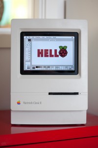
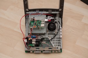
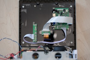
I needed a solution with minimal time effort as I have lots of other things I want to do so I went with a Raspberry Pi Zero W and a PiCamera. Starting as “wash monitor” it transformed to “appliance monitor” as any appliance can be monitored. I have a single Raspberry Pi keeping an eye on both the washing machine and the tumble dryer.

The idea is simple, take a picture, process and count pixels:

  • All black: lights are off and the machine is off
  • Most black: lights are off and the machine is on
  • Few black: lights are on, machine state is unknown

Next, the “lights” and “machine” states are tracked and a notification is sent when “machine” goes from “on” to “off”. Pushover is used as notification service and MQTT for general service monitoring.

There are a few prerequisites that make this solution actually work (yes I know you objected to the idea):

  1. My washing machine is in the basement, ie. in a “controlled light environment”.
  2. The lights in the laundry room are Ikea Trådfri ones activated by a motion sensor and they switch off after a few minutes meaning we will never be stuck in the “lights are on, machine state unknown” state.
  3. Normally no-one enters the laundry room minimising the risk of false positives by a person dressed in black pants standing in front of the camera.

The system works great for me but might be completely useless to you 😀

MJPEG Streamer is used for snapping pictures and ImageMagick for processing. Pictures are cropped to only reveal the display which increases the percentage of non black pixels when the machine is on. Blurring is used to increase specular highlight of the LEDs, a threshold filter is applied making sure we end up with only black and white pixels (and no image sensor noise) and finally the histogram is calculated. The Pi is taped to the wall opposite the machines so it will not move (which would mess up the cropping).

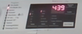
Here is an unprocessed cropped picture of the washing machine display when the room is lit:

0% completely black pixels

(Applying blur and threshold filters now yields a completely white picture from which we can only determine the lights are on)

The same picture with the lights off:

Blur and threshold filters applied:

~84% completely black pixels

Lights off, machine off, blur and threshold filters applied:

100% completely black pixels

Installing and configuring

First clone this the Appliance Monitor repo:

git clone https://github.com/kanflo/appliancemon

You need ImageMagick, Python Requests and Paho MQTT and MJPG Streamer (and of course lots of stuff to be able to build):

sudo apt-get install imagemagick
sudo apt-get install python3-pip
sudo pip3 install paho-mqtt requests
sudo apt-get install build-essential git libjpeg8-dev imagemagick libv4l-dev cmake
git clone https://github.com/jacksonliam/mjpg-streamer.git
cd mjpg-streamer/mjpg-streamer-experimental
make && sudo make install

To spare the poor MicroSD card I use a RAM disk for image processing and a script is provided that adds the RAM disk to /etc/fstab:

sudo ./create-ramdisk.sh

Next, copy sampleconfig.yml and modify as needed (there are lots of comments to guide you). The “image processing parameters” section can be skipped for now.

A start script for MJPG Streamer is included where parameters such as white balance can be set:

sudo /home/pi/appliancemon/mjpg-streamer.sh start

If this fails, check the bcm2835 Video4Linux driver module is loaded and then try to start MJPG Streamer again:

sudo modprobe bcm2835-v4l2

To make it load on boot:

sudo echo "bcm2835-v4l2" >> /etc/modules

Snap a picture:

curl -so image.jpg "http://wash.local:8080/?action=snapshot.png"

Use this image to determine the crop area specified in ImageMagick style (blur and threshold are also IM style, check the ImageMagick documentation for help).

Now try the cropping and calculate the black level. The last two zeroes are “blur” and “threshold” (zero means disable).

./applimon.py -c washconfig.yml -t "290x120+20+410 0 0" ; open image-proc-washer.png
Black level: 0%

Now turn on the machine, turn off the lights and apply blur and threshold:

./applimon.py -c washconfig.yml -t "290x120+20+410 0x6 6"
Black level: 94%

And finally turn the machine off:

./applimon.py -c washconfig.yml -t "290x120+20+410 0x6 6"
Black level: 100%

You may need to elaborate with the blur and threshold parameters to get satisfactory black levels. I use the ones in the sample config for both my washing machine and tumble dryer.

Finally add the following lines to crontab -e:

@reboot /home/pi/appliancemon/mjpg-streamer.sh start
@reboot /home/pi/appliancemon/applimon.py -c /home/pi/washconfig.yml &
@reboot /home/pi/appliancemon/applimon.py -c /home/pi/dryerconfig.yml &

Code on GitHub as always.

ADS-B skygrazing

This is a followup to my previous post about bringing life back to an old Macintosh Classic II.

Having an iconic Mac with a Raspberry Pi inside doing nothing is kind of dull. I wanted the Classic to display something interesting (at least in my point of view) and I did have another Raspberry Pi in the attic receiving ADS-B data and posting to an MQTT feed. How about showing a picture of the nearest aircraft with information about its speed, heading, altitude, distance, bearing and so on?

Without diving too much into the details about ADS-B, what we get from the aircraft is basically speed, heading, altitude and a 24 bit identification number, the icao24. This is a globally unique aircraft ID registered with the International Civil Aviation Organization and we somehow need to convert this into an actual image of the aircraft.

The aircraft’s operator, type and registration are not available in the ADS-B data the aircraft transmits and needs to be pulled from another data source. One excellent source is PlaneBaseNG with about 147k aircrafts. The database consists of an SQLite database which serves us well. Once we have the aircraft type and operator we make a Bing image search and pull an image of suitable size.

The system architecture looks like this, with data flowing from top to bottom

ADS-B receiver
ADS-B client
Proximity radar
Skygrazer

The ADS-B receiver is a Raspberry Pi with an RTL dongle running dump1090.

ADS-B client is a Python script parsing data from dump1090’s feed on port 30003, converting it into a JSON object, adding aircraft data from PlaneBase and publishing on the MQTT topic “`/adsb/radar/json“`.

Proximity radar is another Python script subscribing to “`adsb/json“` while keeping track of which aircraft is the closest one. It calculates distance and bearing, performs image lookup and publishes on the MQTT topic “`adsb/proximity/json“`.

Skygrazer is an application written in SDL2 subscribing to the topic “`adsb/proximity/json“` that downloads and displays the image and flight data received.

The architecture might seem like an overkill but I like the publish/subscribe idea of MQTT, it is a bit like Unix commands. Each one performing one task (and performing it well) and several commands may be chained to create something bigger that the sum of its parts. It also lends itself well to other ideas I have of how to have fun with ADS-B data.

Here is an image of the Classic in action with an A380 from Emirates passing by.

A380 Classic
Airbus A380 image from Wikipedia, Quentin Douchet CC BY-SA 3.0

The project turned out nicely. The Classic runs 24/7 and since the airspace over the southern tip of Sweden is quite busy there is always something going on. I have almost gotten to know some of the aircrafts and flights around here. A quick glance on the Classic and I can tell I am looking at the Air France A380 from Charles de Gaulle to Tokyo. Nerdy huh?

Update! Checkout further use of the ADS-B data in “Commercial pilots control my moonlight“.

Code available here and here on Github.

Meet the Branly IoT platform

These days it seems everybody is tinkering with their own IoT project, I am no different.

It started almost two years ago when I, while looking to build RF nodes, stumbled across the blogs of Nathan ChantrellMartin HarizanovJean-Claude Wippler and Felix Rusu. These guys had built exactly what I was looking for and Nathan even offered the gerbers needed to order Tiny328 PCBs. Tiny328 is an Arduino based RF node fitted with the RFM69C ISM radio. My experience with soldering was limited and my experience with designing PCBs was none, I am a software guy after all. It turned out that reflow soldering PCBs with 0603 components in a hot plate is quite easy (and fun!) once you get the hang of it. Google is your friend.

My fist baby steps in designing PCBs was an Arduino based modem with the RFP69 radio and though hole components, the BranlyPi v2 (v1 was without an external oscillator which caused the ATMega’s buadrate to be off leaving the modem and the RaspberryPi unable to talk).

It was superseeded by the v4 (don’t ask about the v3) which was surface mounted components all the way. Schematics and gerbers are here if you want to build your own.

With all that hardware available it was time to write some software and make two Tiny328s talk. The “hello world” was LowPowerLab‘s “Struct send” and “Struct receive” examples. I soon attached a DS18B20 temperature probe to one of the nodes for some more fun (sic!) data. Software for the BranlyPi was written as well as a python script running on the RaspberryPi listening to the BranlyPi modem.

In all, I had the following setup:

  1. A node fills in data into a struct holding a type field. The types can be “temperature”, “battery voltage measurement” and so on. The struct is transmitted to the BranlyPi modem.
  2. The BranlyPi modem receives the struct and formats in into a textual representation that is sent to the RaspberryPi over UART, eg.
    T:node id:rssi value:temperature

    and

    B:node id:rssi value:battery voltage
  3. The gateway script on the RaspberryPi reads the line above from the UART and posts it to a local Emoncms installation.

The node was placed in my garage with the probe outside. I had (sort of) built my own RF thermometer. Cool! An identical node (with a different node id 🙂 was built and placed indoor. Next, how about building one of those moisture measuring plant nodes? Or one that could tell me if I had forgotten to turn off the lights in the garage at night? I had a feeling the RF network would grow.

So far all is well from a technical point of view. The current software architecture would however need a complete rewrite to be useful, more of that later. Source code and hardware docs on Github.

“Branly” you might ask? Édouard Branly was one of the early pioneers in wireless telegraphy.

Another Raspberry Pi powered Macintosh Classic

The Macintosh Classic is somewhat special to me as it was my first computer I used for other things than just games. Not suprisingly perhaps as the line games was somewhat limited although there where classics like Dark Castle, Apache Strike, Empire and Deja Vu. That aside, I have had a Mac Classic II in my study for years reminding me of where my career in IT started and it was time to pour some life into the old machine (click for hires images or see the gallery at the end).

Hello (again and again)

The obvious choice was to use a Raspberry Pi. Placing Pis in old macs is by no mean a new idea but I wanted to make something different and above all make something as sturdy as the old mac. The newly born Mac should be able to ride the bus as my old Classic did at times meaning I could not just put loose hardware into the box. Things needed to be fastened. I set out with the following specification:

  • Raspberry Pi
  • TFT screen
  • Speaker
  • Internal USB hub
  • External connectors for USB and ethernet
  • Working programmer’s key and reset button
  • Working floppy drive ejector motor
  • External 12V power supply

I had found this 8 inch TFT screen on eBay (update June 5th 2017, I have found a much cheaper variant on AliExpress that by the looks of it is identical) but as you can see the frame has no mounting support. Adding the cabling and driver board with its adapter boards sums up to quite a mess. How do we mount this nicely inside the Classic? Plexiglass to the rescue! I cut out two sheets of plexiglass and placed the TFT screen between them. Glued piexes of plexiglass on the back sheet keeps the TFT screen from falling out. The different boards are placed on spacers mounted on the back side plexiglass sheet. The front and back sheets are held together usings screws.

An 8" HDMI display package
An 8″ HDMI display package

The final part was mounting the “screen module” inside the Classic. As I had thrown the old CRT screen out, it was only a matter of drilling the right holes in the plexiglass screen module and mount it the same manner the original screen was.

Mounting the display package

Next was the mounting of the Raspberry Pi. For this I reused the hard drive bay where I mounted a piece of plexiglass holding the Pi on spacers.

Pi, power and speaker

I wanted to bring back the yawning like sound of a Macintosh ejecting a floppy disk. The idea was to have the Mac automatically eject an inserted floppy with a delay. So how did the old Macs detect the precense of a floppy disk?
There are a number of micro switches sitting in the front of the floppy drive. These will be pressed (or not) when a floppy is inserted into the drive. From right to left they will tell us

  1. Is there a floppy present?
  2. Is is write protected?
  3. Is is a single sided or double sided floppy?

Adding blue and white wires for floppy presence detection

<side note>Floppy disks back in the days had a write protect switch on them consisting of a small piece of plastic that would open or close a hole. An open hole indicated that the floppy disk could be written to. Another hole in the floppy disk indicated if data would be written on one or both sides of the disc. Switches 2 and 3 above would be not pressed if the corresponding hole was present on the floppy disk.</side note>

For this project, I only cared about switch #1. Deciding the floppy drive would never see real action again, I disconnected the switch from the rest of the floppy drive PCB by severing the traces. Soldering wires to the switch and attaching them to the Raspbery Pi GPIO header, the Pi could now sense the precense of a floppy disk. Next was the ejector motor. It runs on 12V (as the TFT screen) and I purchased a relay on eBay that the Raspberry Pi could control.

On the left hand side of the old compact Macs was the programmer’s key and the reset button. The former would enter the debugger built into the computer. I wanted to connect these to the Raspberry Pi so once again I severed some traces. On the the motherboard this time.

For power, I purchased a 12V to 5V converter with quad USB output on eBay. This together with the relay was mounted on a sheet of plexiglass that was mounted on spacers in the back of the computer. The speaker was mounted in a large hole i drilled in (you guessed it) a piece of plexiglass mounted on (guessed it again?) spacers. As the sound quality on the original Raspberry Pi was quite poor I added a USB sound card (also from eBay). I desoldered the microphone connector on the Mac’s mother board and replaced it with a power jack that I connected to the 12V/5V converter. An old Western Digital USB disk power supply provies the 12V needed.

Last but not least, I added two external USB ports and an ethernet port. Both use passthrough cables found on eBay (search for “USB 2.0 A panel mount extension cable 25cm” and “ethernet panel mount extension cable 25cm“. They are mounted on the last piece of plexiglass that is glued to the inside of the case. I reused the holes where the original 220V power cable connector and power switch where located.

Backside USB and ethernet connectors

A simple python script checks the programmer’s key, the reset button and the floppy detection switch and controls the eject motor. Pressing one of the keys will play the lovely old Macintosh Quadra chime. A long press will shut the Raspberry Pi down.

Floppy ejection was a bit tricky. The eject motor is a simple motor and not a servo meaning you cannot tell it to goto a position and back like those servos you have been playing around with using your Arduino. The motor needs to return to (roughly) its original position or it will be impossible to insert a floppy again. I have no idea how this was accomplished back in the days but this simple algorithm (based in parts of my recollection of the old floppy sound) did the trick

  1. Start motor
  2. Wait for lost floppy presence
  3. Wait for 1 second
  4. Stop motor

I am quite pleased with how this mod turned out. There is nothing loose inside the case that can fall over, get tangled up and cause shorts. By accident, the Mac was drop tested from a height of one meter. It survived, nothing came loose.

I have some future plans for HW modifications including a touch screen, replacing the clicking mechanical relay with a transistor and I should add a fuse to the 12V line for safety.

Most of all, I need to add software to make the old Classic actually do something. But that is for a later post.

Update 26th of June 2016, the python script running the show is now on Github.
Update 5th of June 2017, added AliExpress link to cheaper display and eBay links to USB/ethernet passthrough cables.


Gallery