Update! Here is a post with the BOM for the project.
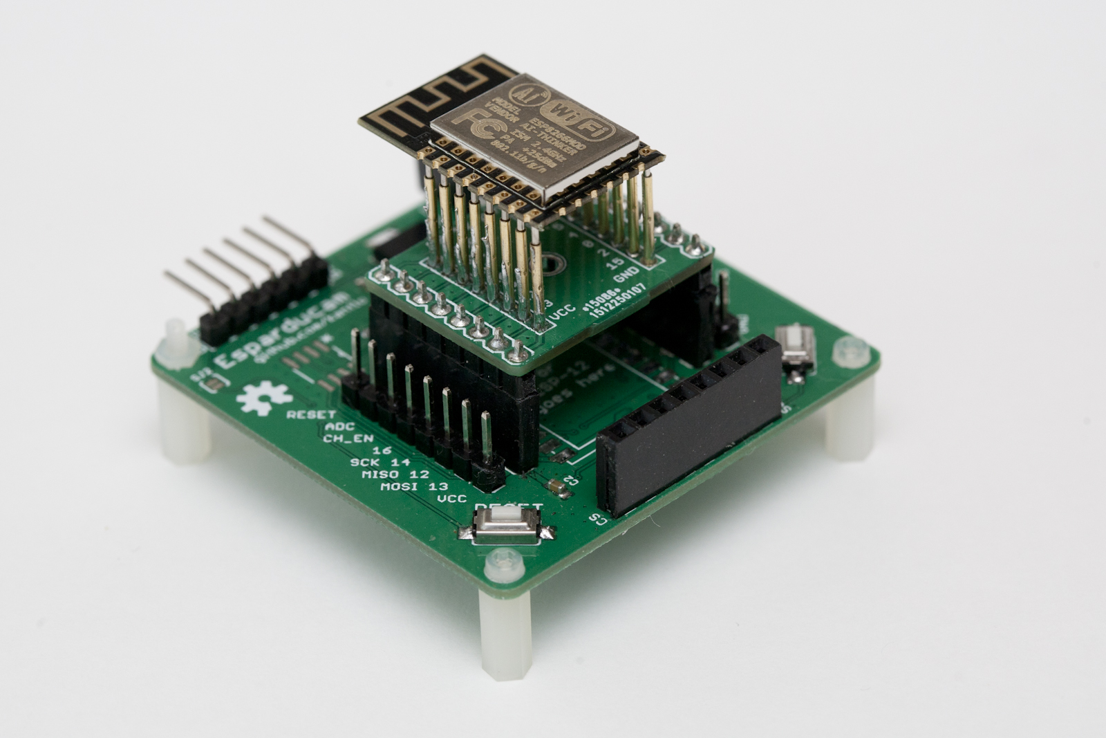
Sometime ago I came across the Arducam Mini which is quite a nice camera module from UCTronics. It is a small PCB with a two megapixel OmniVision OV2640 sensor, an interchangeable lens and an FPGA to do the heavy lifting of image processing and JPEG encoding. Priced at around 24 Euros (lens included) you can easily buy a few without hurting your wallet and combined with an ESP8266 you can build quite a low cost wifi camera. Or several. Because designing and building PCBs is both fun and inexpensive I designed a board to go with the ESP8266/Arducam Mini combo, aptly named the Esparducam. And uniquely named too, try googeling for “esparducam“. Heck, even the domain name is available at the time of writing 🙂
Anyhow. The Esparducam board is a development board for the Arducam Mini module and is quite well suited for ESP8266 development in general.
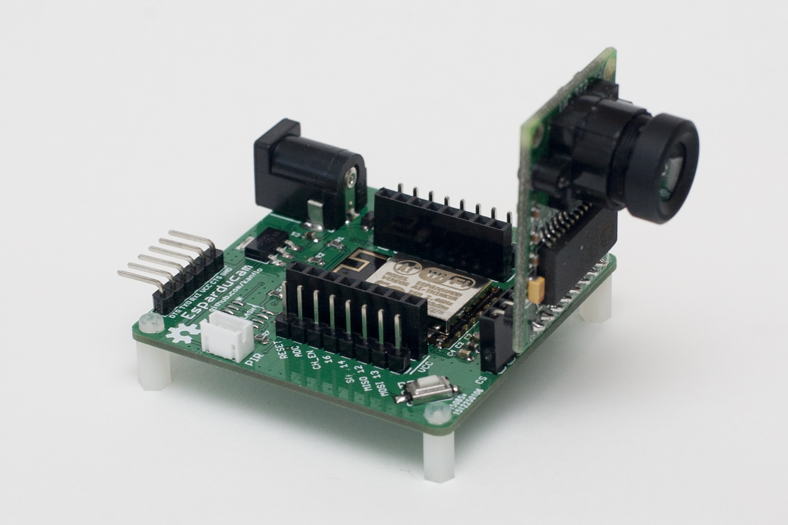
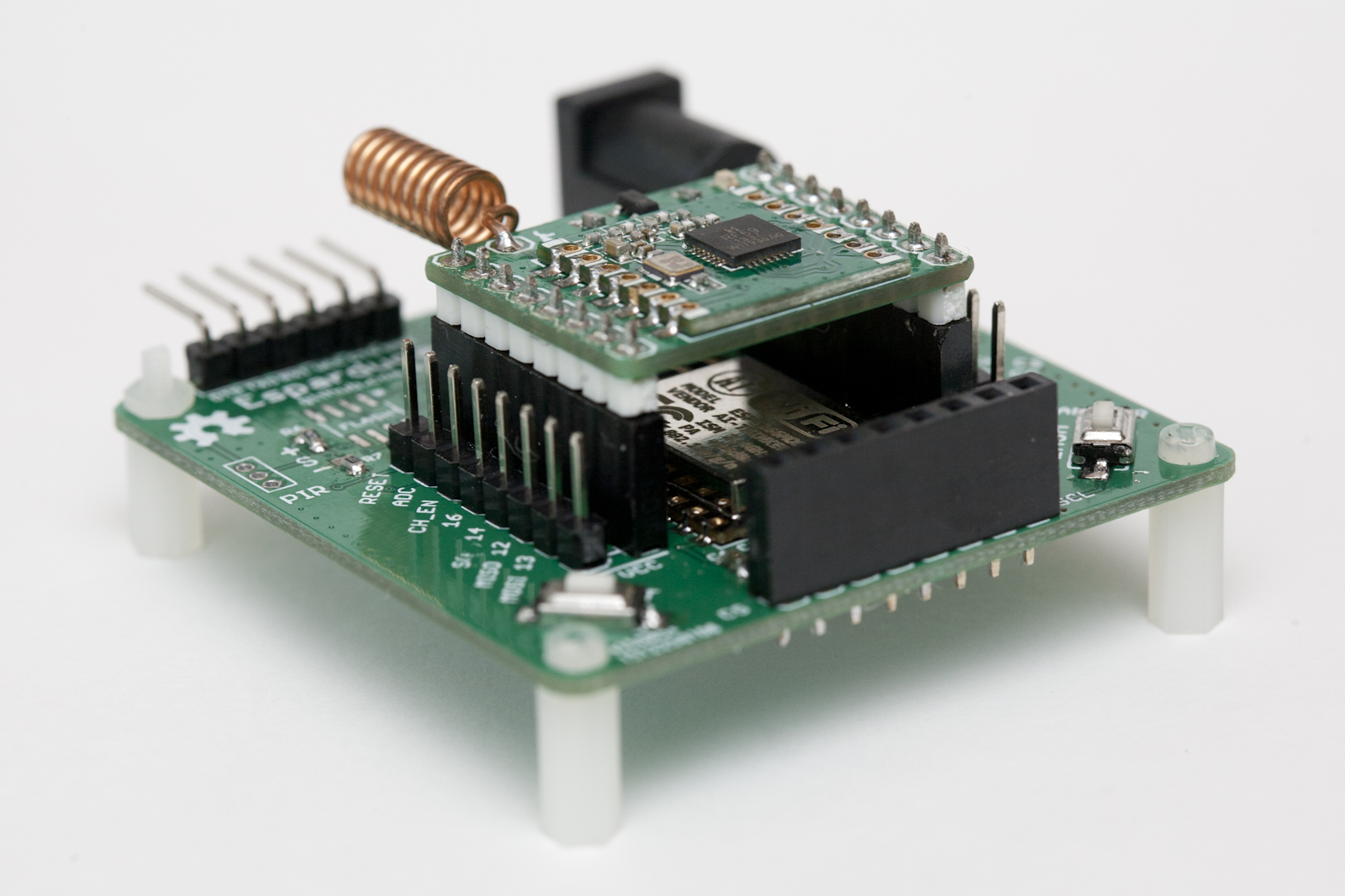
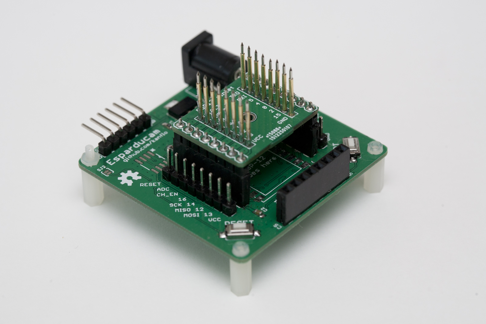
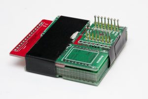
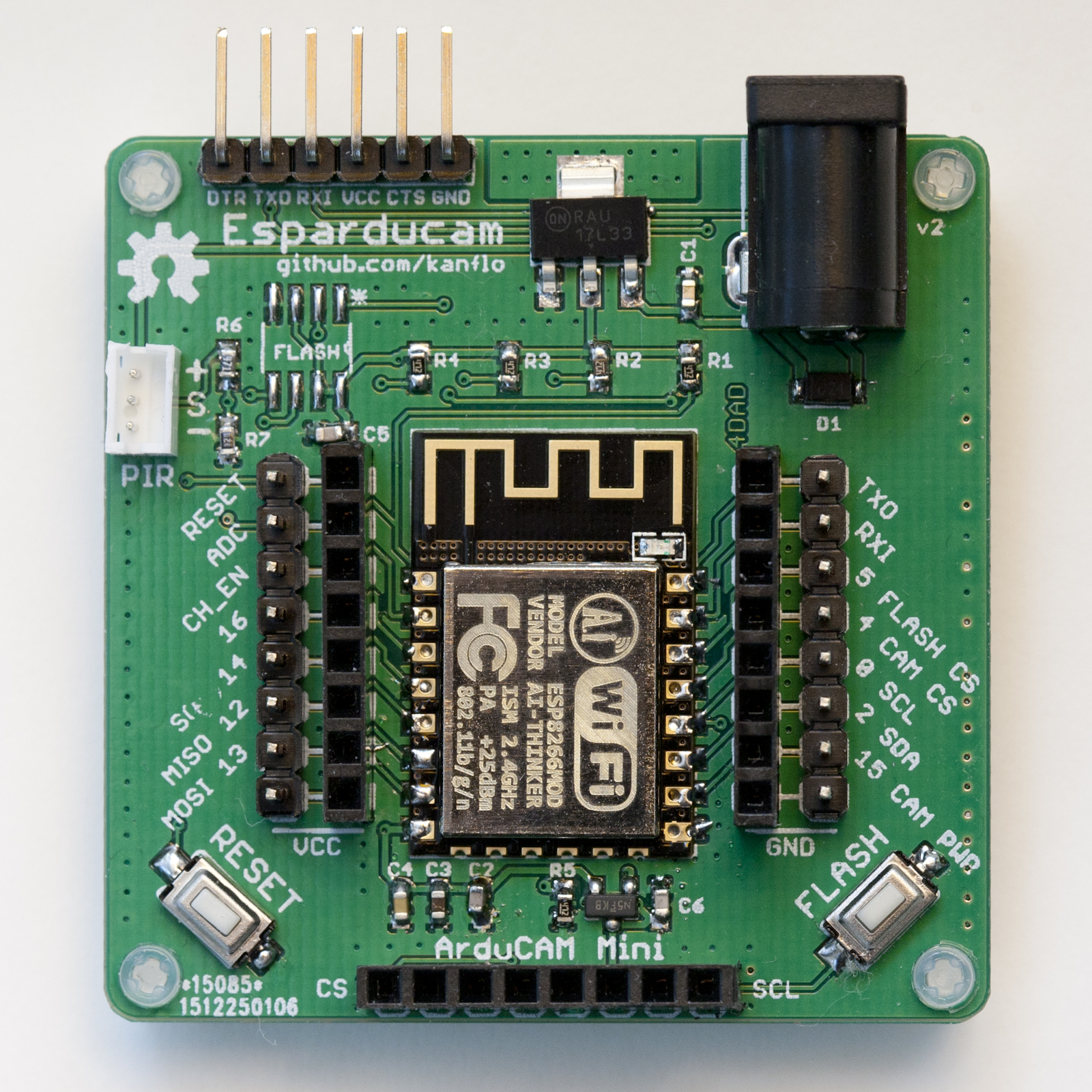
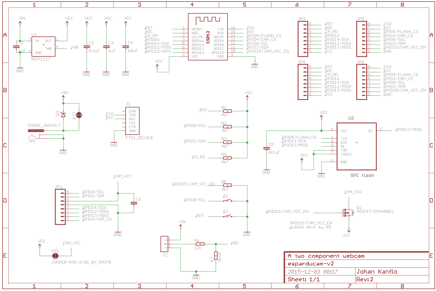
The board is powered through a barrel connector at a minimum of 5V (upper limit untested) and all the IO pins on the ESP8266 are available on pin headers. The double rows are intended for the design of small breakout boards that sit on the inner 0.1″ aligned headers while the outer headers allow for connecting logic analyzers/oscilloscopes and so on. The Arducam Mini module plugs right into the front header and the standard FTDI connector is at the back of the board.
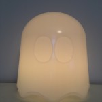
Image quality is, imho, quite decent at this price point, here are a few samples.


An optional SPI flash can be mounted for image storage and you can connect a standard eBay PIR module to the white JST header next to the FTDI connector if you want to build a motion triggered camera.
I am no hardware engineer but if you are and you find any silly design mistakes please let me know.
You can order the Esparducam board form DirtyPBCs and I would love to know if you build one. I plan to build a few for house monitoring, kite photography, reading my water meter and whatever else I can come up with.
The demo application listens to port 80 for HTTP GETs and will capture and return an image. It also has a command line interface on the serial port and the command ‘upload:<ip number>’ will capture an image and upload it via HTTP. A Python script is included that will receive and display the image using your system’s default image viewer. Note that the demo application is just that, a demo application. It does not handle simultaneous clients, errors or anything else that occurs in the real world.
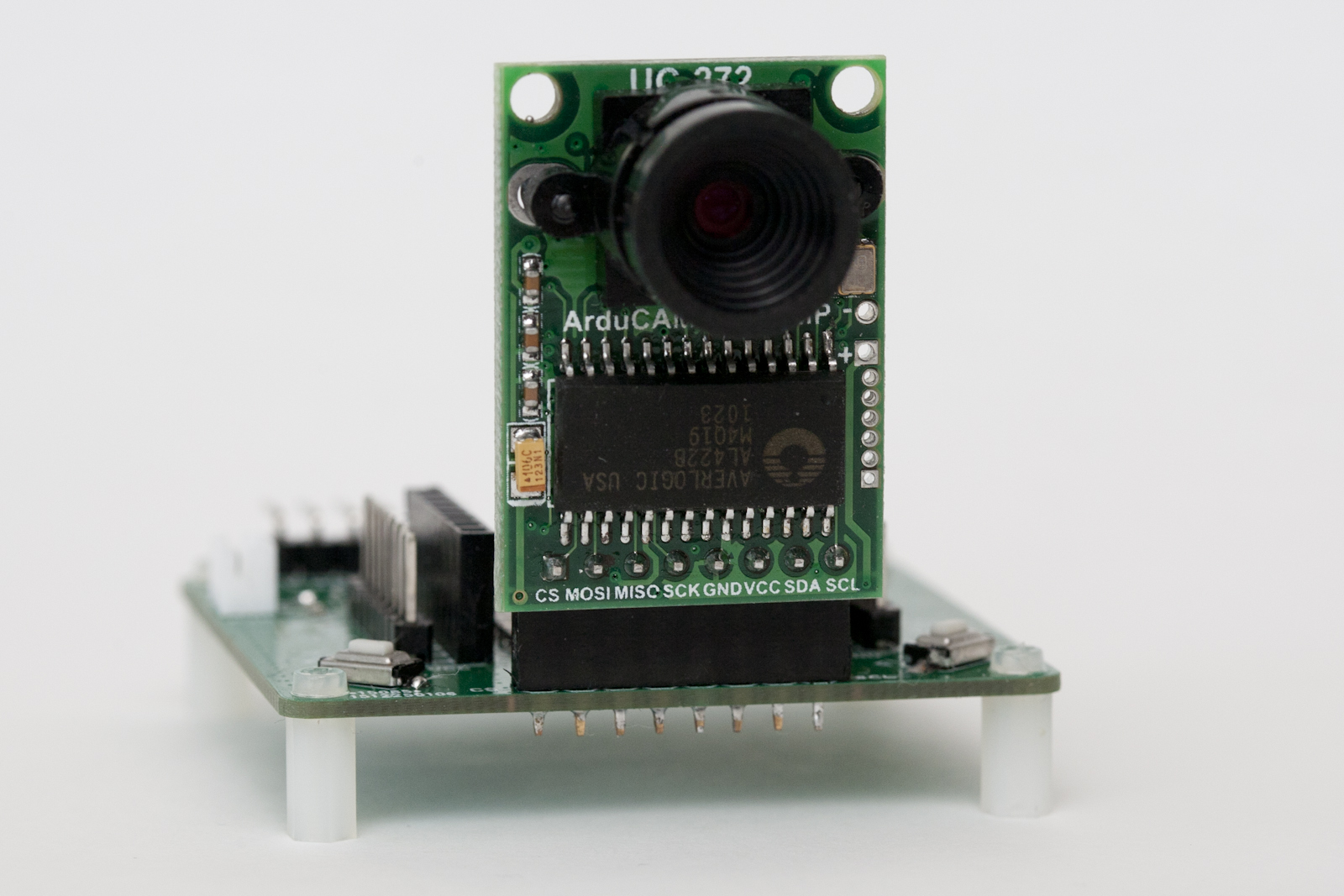 Lastly a note about the lens. It uses a mount called M12xP0.5 and there are plenty of lenses to choose between. The one included with the Arducam Mini module has about the same field of view as a normal 50mm lens on a full frame DSLR. I would recommend getting a 3.2mm lens or shorter for some more wide angle if you plan to use the module for surveillance applications. The 3.2mm lens (called LS-40136) can focus at a very short distance making it a candidate for water meter reading applications.
I have yet to try the even shorter ones like the LS-20150 at 2.8mm or the LS-40166 at 2.6mm.
The Esparducam turned out so nice it became my preferred ESP8266 development board, why is a different post.
Code and hardware schematics as always on Github.