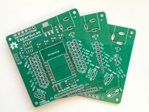
I have had some questions about the possibility to purchase Esparducam boards and also about the bill of material. While I am looking into selling spare boards, here are some instructions about building the boards. Here is the link to order the PCBs [dirtypcbs.com].

If you have never tried building surface mounted boards yourself I highly recommend you try it! I started here [nathan.chantrell.net] and googled my way from there.
Here is the BOM with some eBay links:
C1 1uF capacitor 0603
C2 0.1uF capacitor 0603
C3 1uF capacitor 0603
C4 10uF capacitor 0603
C6 0.1uF capacitor 0603
J1 6 pin 2.54mm male header (angle) [eBay]
JP1 8 pin 2.54mm female header (for the Arducam Mini) [eBay]
JP9 Power jack 5.5×2.1mm [eBay]
R1 4k7 0603
R2 4k7 0603
R3 4k7 0603
R4 4k7 0603
S1,S2 Momentary switch [eBay]
U1 NCP1117 (or LM1117) 3.3V regulator [eBay]
X1 ESP-12f
The following parts are optional depending on what you want to do with your board:
Reverse current protection
D1 SOD-123FL, schottky diode for reverse current protection [eBay],
If you feel brave you can bypass the diode by placing a blob of solder across SJ2 on the back of the board.
Adding motion detection
If you want to attach a PIR [eBay] you need:
J2 JST ZH connector, 3 pin [eBay]
R6 220k 0603
R7 100k 0603
R6 and R7 was going to be a voltage divider that I messed up leaving R7 optional. Please note that the PIR does not work at 3.3V. To bypass this without adding a 5V regulator I simply feed the PIR with the raw board voltage which in my case is 5V.
Controlling power to the Arducam Mini
If you want to be able to control the power to the Arducam Mini board you need Q2 and R5. If you feel ok to have power constantly enabled simple place a blob of solder across SJ1 at the back of the board.
Q2 P mosfet, SOT-23 [eBay]
R5 4k7 0605
External flash
The external SPI flash is also optional. Please note that the footprint is somewhat too narrow, some flashes might not fit.
U2 SPI flash SOIC-8
C5 0.1uF 0603
Adding header pins
These optional headers are for attaching add-on boards or pins for taking measurements
JP3, JP6 8 pin 2.54mm male header
JP4,JP5 8 pin 2.54mm female header
That’s it, good luck!
Pingback: Building a low cost wifi camera – Johan Kanflo
> Please note that the PIR does not work at 3.3V
Just connect 3.3V to Pin 3 on the JP1 to bypass the onboard 3.3V voltage regulator on the hc-sr501. 🙂
Thanks for the tip!
Your BOM doesn’t include the 8266 or OV2640 themselves? Makes me wonder what else the BOM is missing. Also, any plans to make “kits” for this? If so, I’m in for two. Not really wanting to scrape up the materials and print the boards on my own :/
The ArduCAM module is not included as the board can be used for more that camera applications but the missing ESP is sloppiness on my part. I will check the BOM for consistency, thanks for pointing it out. As for the availability of Esparducam boards, I will see what I can do.
Cool. As I said on the AA project, I’d love to help from North America with a kickstarter or other similar “bulk” project if there’s interest. SMD parts are definitely out of my league.
Johan, VERY interesting and THANK YOU for your effort and work. Clean product and wonderful presentation!!
Thanks!
As @tedder – yup, me too.
Just got my +/-10 dirty boards delivered from the slow boat in today! (got exactly 10 fwiw..)
Boards look lovely (got mine in some sparkfun-esque red) and thanks for the great project platform, really looking forward to this weekend!
Nice! Please send pictures 🙂
Here’s a few, including the batch of the daughter boards… that I made backwards :/
https://www.dropbox.com/sh/vhsvce6eawzzjvf/AAD3_CW3K3tKKOOLMzZ-ct4Ga?dl=0
Looks nice. Seems you etched the daughter boards. I haven’t tried that, would reduce the turnaround time I guess 🙂
how to connect arduino uno? and use code upload?
Hello Johan,
the link to dirtypcb is not there.
Could you provide this information ?
Thanks
Holger
Thanks for pointing that out, here’s the link: http://dirtypcbs.com/store/designer/details/4909/724/esparducam
Johan,
Thanks for sharing your Esparducam with the world, great project. I have one question that I can’t seem to find an answer for though. Can you suggest an external SPI Flash chip for use with the ESP8266? I know you mentioned lead spacing which doesn’t concern me as I find the 150 mil package size fits your board layout but there are so many other options. I assume the chip needs to operate at 3.3V but I’m really in the dark after that.
Thanks for your time
Thanks! Any 8 pin SOIC SPI flash should do as long as the pinout is the same, which (from a quick glance) seems to be the case. https://uk.farnell.com/w/c/semiconductors-ics/memory/flash?memory-case-style=soic&no-of-pins=8pins&st=spi%20flash&pageSize=100