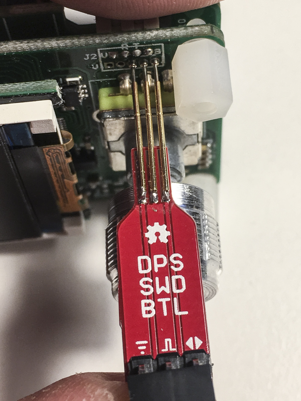
On newer DPS:es, the SWD connector is a JST-GH (1.25mm spacing that is) which translates to “really tiny”. The annular rings where you need to apply solder and heat for adding wires are even smaller. This is why the OpenDPS SWD Bottle is handy. Add three P50-E2 pogo pins, and connect to your favourite SWD debugger.
One hand SWD debugging
BOM
1x “DPS SWD BTL” PCB
3x P50-E2 pogo pins (about €5 for 100pcs on AliExpress)
1x 3 pin 0.1″ male right angle header
3x F-F dupont cable
Mounting
Add solder to each of the three exposed pads where the pogo pins will be mounted.
Hold one pogo pin with a tweezer or small plier an align along the pad.
Apply heat on the pad and when the solder reflows, gently push the pin in place and wait for the solder to cool down.
Repeat for the second pin and check alignment of the two pins on your DPS.
Repeat for the third pin and check alignment on your DPS.
Solder the 0.1″ header on the reverse side of the pogo pins.
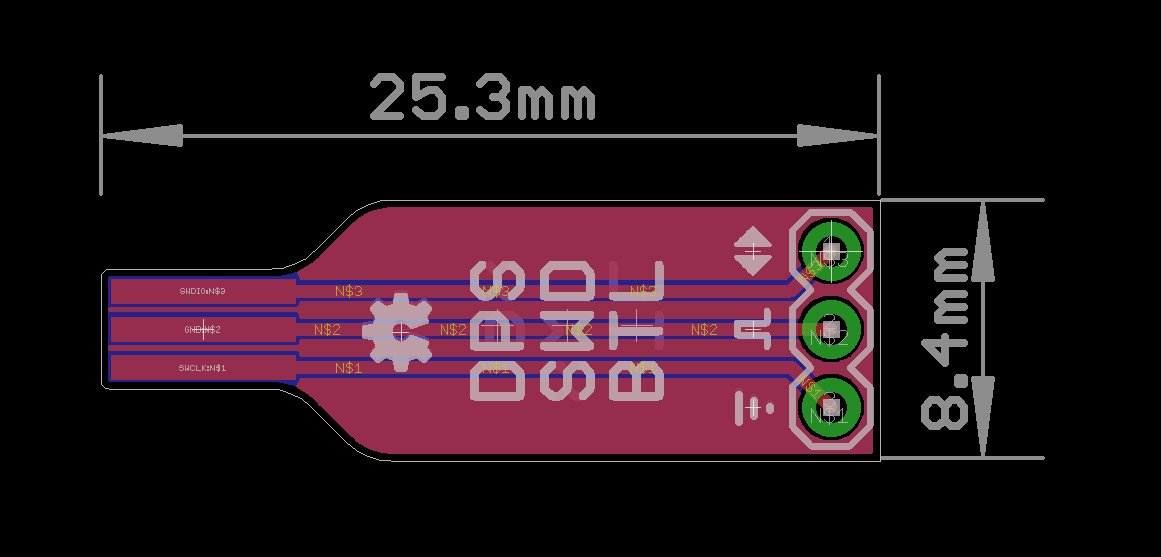
Well it looks like a bottle, doesn’t it?
Using
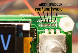
The pinout is described on the silk and you should be able to make out which is GND, SWCLK and SWDIO with a little imagination 🙂 The DPS BTL shall be interfaced with ground to the left touching with the middle annular ring of the DPS SWD connector. See the top image.
Soldering the right angle header on the suggested side helps you in pressing the adapter against the DPS with one hand only.
Want one?
I have been playing with the thought of selling some of my prototyping stuff on Tindie or some other maker market place for some time and happen to have an ample supply of DPS bottles as I sprinkled a prototyping board with them. If you are interested in buying one you can contact me via my GitHub page.
1x DPS SWD BTL with pogo pins and right angle header mounted: €5
3x dupont cables: €1 (slight rip-off, I know. I can sell these as a courtesy but do not wish to drain my own supply)
Shipping and handling: €13 for traceable and insured or €3 for non traceable a non insured for all parts of the world except Sweden
Or you can gerberize the Eagle project, order and build one yourself as this is OSHW, as always.
When I released the AAduino (original post here) last year Ididnotreallyexpectthecoverageitrendered. Even my WordPress server was surprised as referrals from Hacker News and others brought it to its knees. Building on the ATMega 328 was a natural choice at the time but I really wanted to move to 32 bit ARM micros. One of the reasons is the great debug support available using the impressive Black Magic Probe or cheap ST-Link clones. Gone are the days of my youth when an ARM JTAG debugger would set you back €2000.
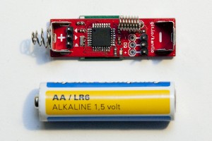
Original AAduino
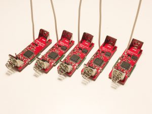
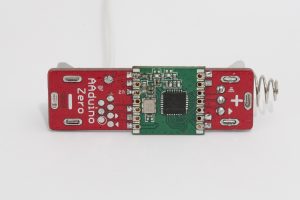
New AAduino Zero, lots of ’em
Crowd Sourcing the AAduino Zero
So here we are today, the AAduino has evolved into the AAduino Zero that will start crowd sourcing over at Crowd Supply soon. Sign up today and get notified when the campaign kicks off!
Test points for power, SWD and UART to the left
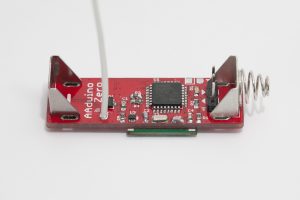
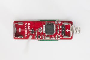
Older prototype without serial flash
Older prototype without serial flash
I have previously written “soonish” about the start of the campaign but now I can say “soon” with confidence 😉 I have a few hand built prototypes that are working as expected and will go into production with no design changes. I have a quotation from Seeed Studio and the campaign will launch as soon as the final details have been decided upon (pricing being one of them).
Specs
The form factor is identical to the original AAduino, as is the RFM69CW companion, but the rest has changed. The micro is now an STM32L052, the temperature sensor is a TMP102, there is polarity protection and also a serial flash which will enable wireless firmware upgrades or data logging applications. A 32kHz oscillator drives the real time clock of the STM32 and for extendability there is a 1 pin IO port (yes, one pin only). The UART (for flashing and debug output) sits on a convenient 0.1” header as on the original AAduino and there are test points for power, SWD and UART.
Here are the full specs:
STM32L052 micro controller with 32kb flash, 8kb RAM, 2kB EEPROM
Minimum power consumption: 8μA. Yes, eight microamps
Software & demos
Now that the hardware design is frozen I am working on the software including some demos. The AAduino Zero is currently programmed in C using the lovely libopencm3 project. I am planning on adding Arduino IDE support as not everyone are comfortable with installing toolchains, running makefiles and so on.
The first, and most obvious demo, is to get one AAduino Zero talking wirelessly to another one acting as a gateway, forwarding the received packets to eg. a Raspberry Pi. We will see about the next demo implemented but it might be an energy monitor as the one I was using broke down recently 😉
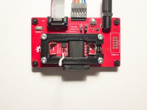
A tiny test fixture companion
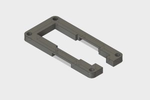
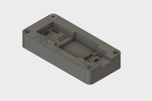
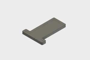
In addition to the AAduino Zero, I designed a small test jig to go with it. While the jig is useful for SWD flashing and debugging, it is not required for application development; the AAduino Zero will have an “Arduino style” serial boot loader. I designed three parts in Fusion 360 to hold the AAduino Zero in place:
Holder
Jig
Key
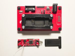
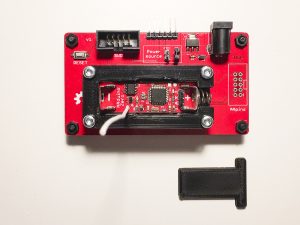
The “holder” is placed on top of the “jig” and both are fastened to the PCB using M3 bolts. The AAduino Zero goes into the holder and is locked in place with the small “key”.
Pogo pins connect the device to the SWD and FTDI ports on the back and provide power from the DC jack. The unpopulated “AApins” connector is meant for a small hand held pogo pin programming adapter currently in production. It has not been decided if the jig will be included in the campaign but as mentioned previously, it is not required for working with the AAduino Zero.
Open Source?
As always, very much so. Both hardware and software will be published on on GitHub, with one small caveat. The Eagle design files will only be published once the campaign is over and the AAduino Zeros start reaching the backers.
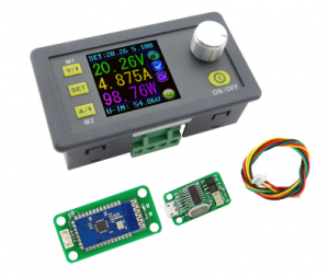
It’s exciting to see the continued development of the DPS5005 and ‘3005. Today Rd Tech released a version with USB/Bluetooth connectivity and I just ordered one to make sure OpenDPS runs on it. The new version seems be fitted with a JST has a JST GH connector which makes connecting an ESP8266 or a serial port a bit easier. It also has different MOSFETs by the looks of it.
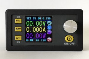
Stock DPS, now with comms
New MOSFETs
Now I only need to wait 25-36 days for shipping. The wait is over and with a minor tweak (DAC needs to be disabled when turning off the output) OpenDPS is fully functional on the new DPS5005 “communication version”.
UART changes
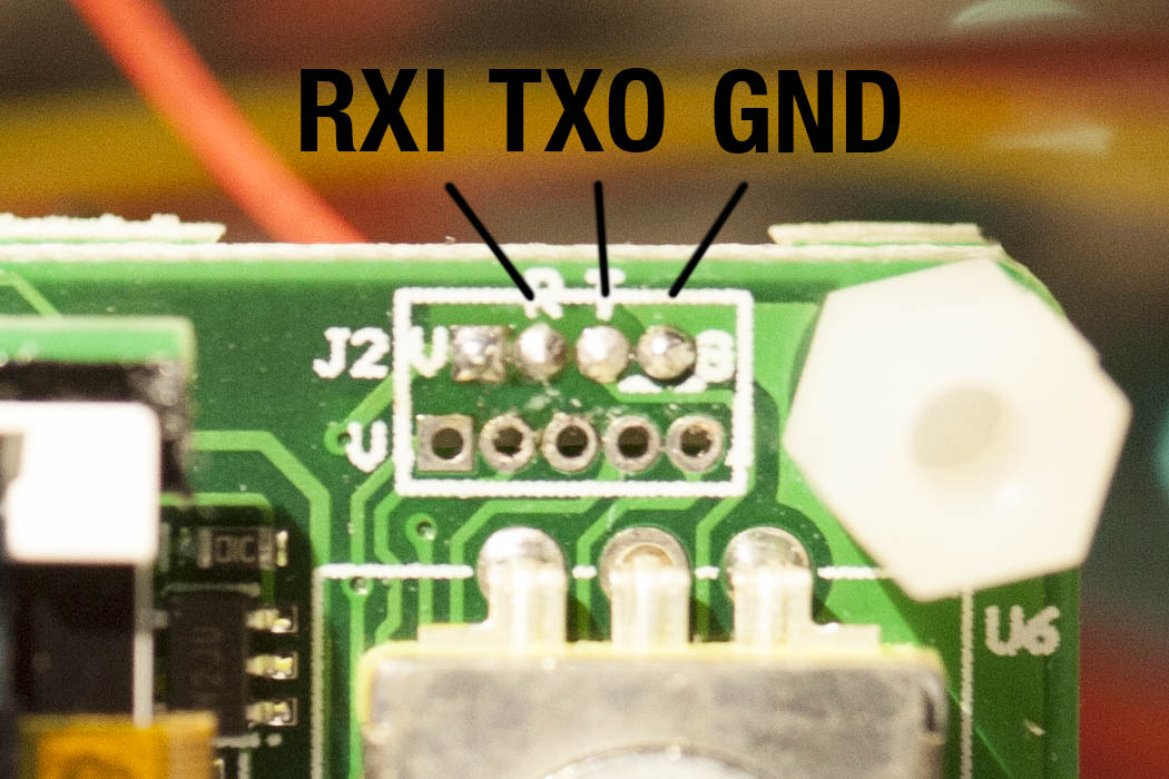
There is no need to solder the UART anymore and you get a cable with the device. You can cut the cable in half to connect to your ESP8266 or FTDI-adapter but I recommend buying a set of cables and connectors from eBay. Search for “10SET JST GH Connector plug with Wires Cables” and get the JST-GH 4 pin kit. The pinout of the cable depends on what end you insert into your DPS (as both ends have female connectors). Thus, I will not say “red is VCC” as it will be “red is GND” if you connect the other end and observe the holy smoke. Look at the pinout below and determine which wire is which. The silkscreen is “V R T B” which I think should have been “V R T G“.
JST-GH UART
RXI indicates that this is the RX input (sic!) of the DPS5005. and TXO is the TX output (re-sic!) of the DPS5005. People have mixed up RX and TX for ages, calling your signals RXI and TXO will put an end to it. To the left of RXI is VCC which in the previous version could not power an ESP8266. I have not checked if the regulator has been changed to something more powerful in this version.
JTAG changes
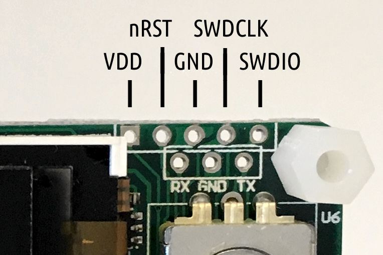
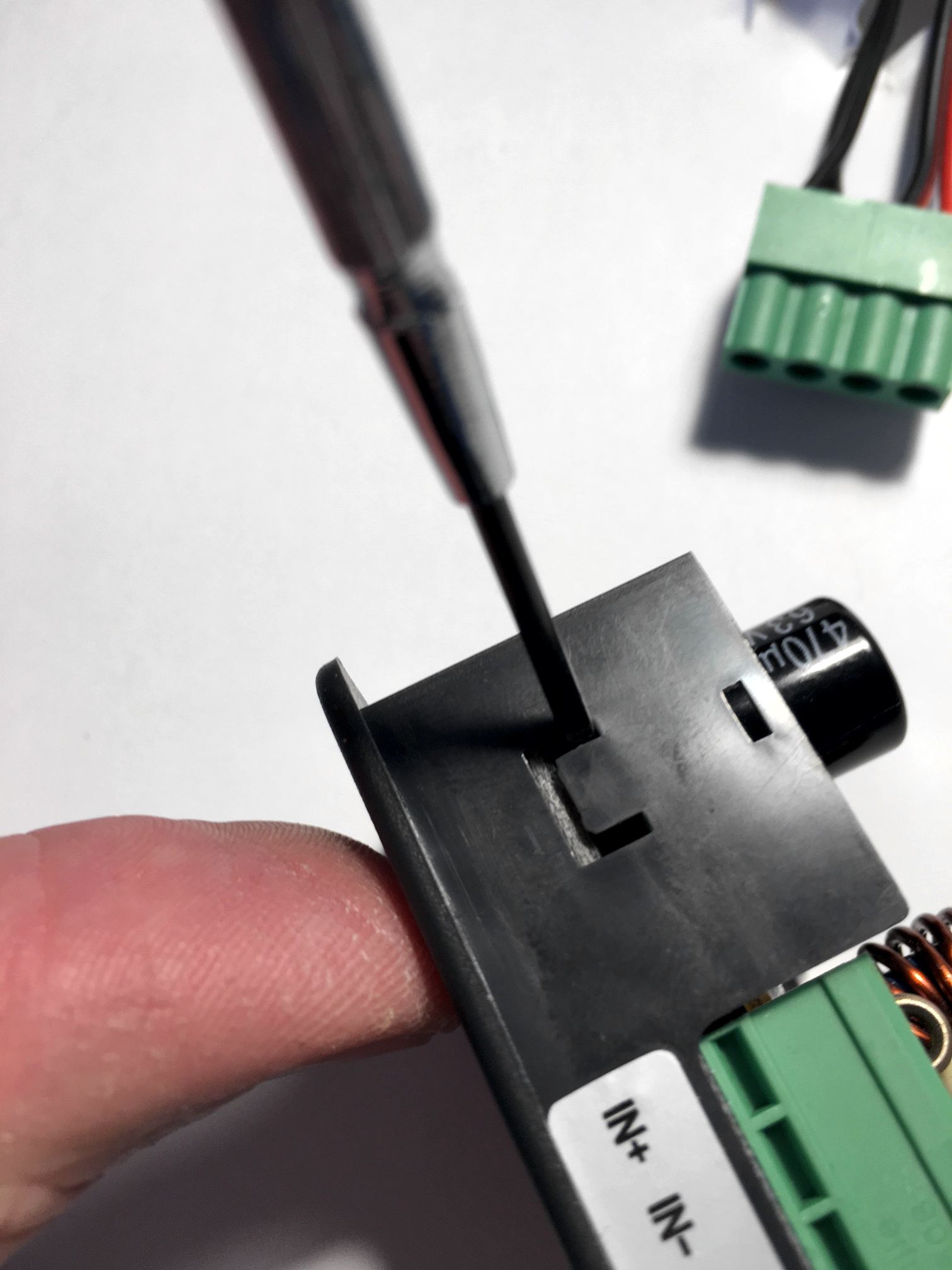
The JTAG connector on these new devices is called JST-GH and has a tiny 1.5mm1.2mm, 1.25mm spacing and there is not room for running the JTAG wires toward the back of the device which makes a permanent JTAG solution cumbersome. When flashing, I simply pressed three test needle probes agains the GND, SWCLK and SWDIO connectors. Then again, most people will not need permanent JTAG but we all want a easy upgrade option for OpenDPS.
JTAG pinout, same but tinier
UART firmware upgrades
The solution is a bootloader that accepts firmware upgrades over UART. When unlocking your stock DPS, use whatever needles or pins you can find to connect GND, SWCLK and SWDIO and flash the bootloader. Then use dpsctl.py for the firmware upgrade:
% make -C opendps bin
% dpsctl.py -d /dev/ttyUSB0 -U opendps/opendps.bin
If you accidentally upgrade to a really b0rken version, the bootloader can be forced to enter upgrade mode if you keep the SEL button pressed while enabling power.
The display will be black during the entire upgrade operation. If it stays black, the bootloader might refuse or fail to start the OpenDPS application, or the application crashed. If you attempt the upgrade operation again, and upgrading begins, the bootloader is running but is refusing to boot your firmware. But why? Well, let’s find out. If you append the -v option to dpsctl.py you will get a dump of the UART traffic.
Communicating with /dev/ttyUSB0
TX  9 bytes 7e 09 04 00 27 86 0c b2 7f
RX 9 bytes 7e 89 00 04 00 03 66 0f 7f
The fourth byte from the end in the received data (0x03 in this example) will tell us why the bootloader refused to boot the firmware. See protocol.h for the different reasons.
Still not affiliated with Rd Tech. Would appreciate a discount though *cough* *cough* 😉
Some time ago I found the DPS5005 while browsing AliExpress for programmable power supplies. To be honest, I dismissed the ‘5005 since it was not a complete product. Then HAD wrote about it in december last year and after watching YouTube user @iforce2d’s video I just had to get one. The overall impression was quite good but the software was a bit cluttered and the DPS5005 could not be instrumented via a serial port (or wifi). Looking closely at the sandwich PCB design I noticed the DPS is powered by an STM32, which is pretty much what I expected. And so begun the OpenDPS project, a free firmware replacement for the DPS5005 and friends.
OpenDPS, wifi connected
This write up of the OpenDPS project is divided into three parts. Part one (this one) covers reverse engineering the stock firmware and could be of interest for those looking at reverse engineering STM32 devices in general. Part two covers the design of OpenDPS, the name given to the open DPS5005 firmware. Part threecovers the upgrade process of stock DPS:es and connecting these to the world. If you only want to upgrade your DPS you may skip directly to part three.
Reverse engineering the DPS5005
The reverse engineering of the DPS5005 can be summarised as “bring up of the STM32 based DPS5005 hardware and writing an application for it”. This is pretty much my day job but I always have the hardware schematics and the hardware design engineer at hand. This time, obviously, I had neither which was a bit more challenging. So where does one start? Looking at the PCB, I quickly found the serial port. That was a dud, completely silent. Fake port! I later realised the DPS5005 stock firmware does not even initialise the serial port. The STM32 is covered by the TFT display, which in turn is soldered using eight pins. As I did not have the time to play with iron and solder wick I resorted to a metal saw and promptly sawed the TFT display off (please note this is not the unit in the pictures below).
Top: SWO pinout, UART below
Warranty voided, oh there actually was none to begin with. Having the STM32 in the open quickly allowed me to identify the five test points at the top of the PCB, the expected SWO trace port. But had the producers locked the SWO port when flashing the firmware? Luckily, no.
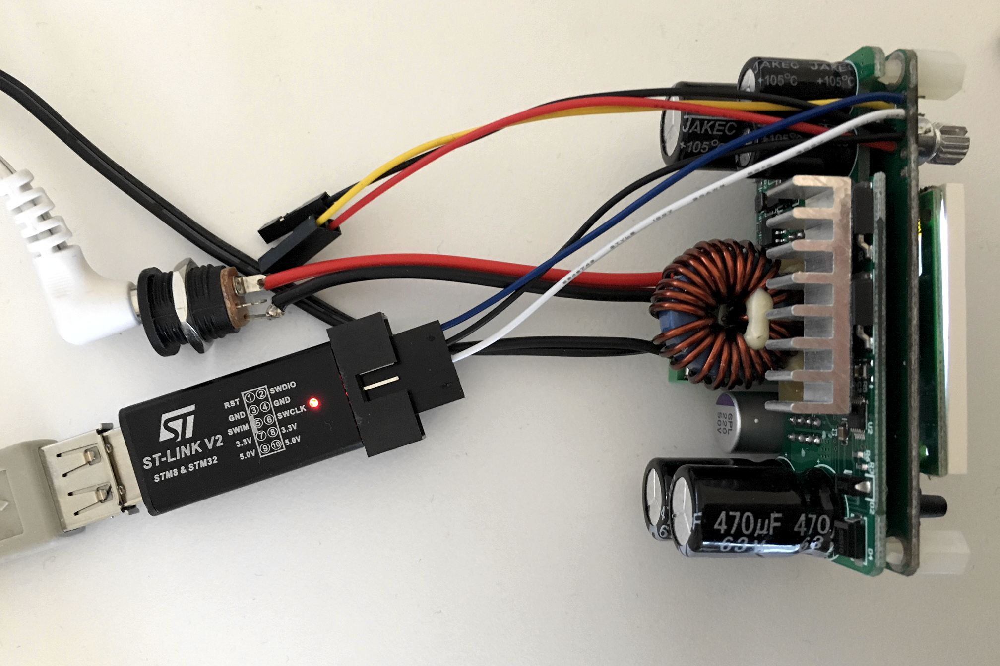
Debugger connected
After some soldering, connecting an STLink clone and selecting an appropriate OpenOCD configuration for the STM32F100, I had a go at it:
% openocd -f interface/stlink-v2.cfg -f target/stm32f1x.cfg
GNU ARM Eclipse 64-bits Open On-Chip Debugger 0.10.0-dev-00498-gbbfb673 (2016-10-28-19:13)
Licensed under GNU GPL v2
For bug reports, read
 http://openocd.org/doc/doxygen/bugs.html
Info : auto-selecting first available session transport "hla_swd". To override use 'transport select <transport>'.
Info : The selected transport took over low-level target control. The results might differ compared to plain JTAG/SWD
adapter speed: 1000 kHz
adapter_nsrst_delay: 100
none separate
Info : Unable to match requested speed 1000 kHz, using 950 kHz
Info : Unable to match requested speed 1000 kHz, using 950 kHz
Info : clock speed 950 kHz
Info : STLINK v2 JTAG v17 API v2 SWIM v4 VID 0x0483 PID 0x3748
Info : using stlink api v2
Info : Target voltage: 3.245093
Info : stm32f1x.cpu: hardware has 6 breakpoints, 4 watchpoints
Yay! Next I connected to OpenOCD to examine the target:
% telnet localhost 4444

> halt
> stm32f1x options_read 0
Option Byte: 0x3fffffe
Readout Protection On
Software Watchdog
Stop: No reset generated
Standby: No reset generated
User Option0: 0xff
User Option1: 0xff
So “readout protection” is enabled which mean you cannot read the firmware from flash. Not a biggie as I was not interested in the stock firmware in itself, only what it controlled. So what would be needed to create the OpenDPS firmware?
Learn how buttons and other IOs are connected.
What STM32 peripheral drives what function?
Controlling the output voltage (controlled by the DAC?)
Current limiter (maybe ADC?)
Measuring input and output voltage (definitely ADC)
Dimmable TFT (not needed 🙂
Write a TFT driver
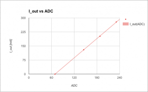
To assist, I created a Python script (ocd-client.py) connecting to OpenOCD for dumping various STM32 device registers. Eg, by dumping the entire DAC register area I could determine the DAC was in use. The buttons I could identify by dumping the GPIO input registers, pressing the button and dumping the registers again. The entire GPIO setup can be recreated by this script and I learned the output voltage really is driven by the DAC. The TFT backlight is driven by timer 4 and the output current, input voltage and output voltage are measured using ADC1 on channels 7, 8 and 9. The 1.44″ TFT is an ILI9163C and I used @SumoToy’s driver for this. The SPI select pin for the display is grounded which is a clever way of saving one pin for designs where there is only one device connected on the SPI bus. Additionally, the display does not use the MISO pin. The most important thing now was how to control the DAC to set a desired output voltage, how to interpret the ADC1 values measuring the output voltage, current draw and input voltage. Normally, one would look at the schematics to figure out what an ADC reading means but in this case I had to reverse engineer that. I simply connected a multimeter, tried a few settings on the stock firmware, observed the ADC1 reading and plotted the result. Next, I created a simple application using the lovely libopencm3 and tested in on a “Bluepill” before wiping the DPS5005. Telnetting to port 4444 again I tried:
> reset halt
> flash erase_address unlock 0x08000000 0x10000
Device Security Bit Set
stm32f1x.cpu: target state: halted
target halted due to breakpoint, current mode: Thread
xPSR: 0x61000000 pc: 0x2000003a msp: 0x20000800
stm32x device protected
failed erasing sectors 0 to 63
Failed! Hmmm, let’s do a power cycle, restart OpenOCD and try that again.
Now that’s better! I am not sure why it fails the first time, it did so on both my units but succeeded on the second attempt. A simple ‘make flash’ and the display showed my test pattern and the power output was at the expected 5V. Mission, partly, accomplished! I could reflash the DPS5005 and control the voltage setting. Time to write a proper application. More in part two.
This is the second part about hacking the DPS5005. Part one covers the reverse engineering of the DPS5005 and part three covers the process of upgrading stock DPS5005:s to OpenDPS.
The goal of OpenDPS is to reflash the stock DPS5005 (and friends) with a firmware that has the same functionality, has a less cluttered user interface and is remote controllable via wifi or a serial port. The application needs to respond to user input both via buttons and the serial port and also via ADC readings telling us if the current draw is larger than what we allowed. Buttons and UART RX are handled using interrupts and obviously the ADC needs to be interrupt based too for fast response (and less smoke). Responding to user input and TFT drawing can be left to the application context.
Before…
…and after.
System Overview
The following modules are used in OpenDPS:
event – uses a ring buffer for storing events from the interrupt context to be handled in the application context. Events are button presses, received bytes on the UART and over current protection triggers
The application in opendps.c sits in a busy loop waiting for events to arrive in the circular buffer. Button presses, serial RX and over current protection events are placed in this buffer. The application calls the UI module that updates the UI with fresh measurements every 250ms. User input is also handled in the UI module. Events are 16 bit integers encoding the event type and optional event data. For the UART RX event the data obviously is the received byte. For button presses we also include information telling us if the press was a long press.
ADC and DAC Management
As I did not have the schematics at hand I had to reverse engineer the formula to calculate voltage/current based on ADC readings. I did some measurements and plotted in a Google Docs spreadsheet to find out
V_in(ADC1_IN8) – given a reading on channel 8, what is the input voltage?
V_out(ADC1_IN9) – given a reading on channel 9, what is the output voltage?
V_out(DAC) – what is the output voltage given a DAC setting? (and the inverse)
I_out(ADC1_IN7) – given a reading on channel 7, what is the current draw? (and the inverse)
I_out(ADC)
DAC(V_out)
ADC(V_in)
To reduce complexity in the ADC IRQ handler, I pre calculate the ADC value that corresponds to the dialled current limit to quickly determine if we went over the limit. Here I ran into some issues as the ADC reading of the current draw differed between the two ‘5005s I had at hand. One of the units reported the wrong current draw which was tracked down to a different value when no current was drawn at all. The remedy is to take the first 1000 samples at system startup to calculate the ADC value for 0.00mA current draw and compensate in the calculations (see adc_i_offset & friends in hw.c)
Additionally, I currently collect a number of “over current samples” before triggering the OCP. This scheme needs some investigation.
Persistent Storage
User settings need to be persisted and this is taken care of by the past (parameter storage) module. This module uses two blocks for storing data. One is the “current block” and when it gets full a garbage collection is performed and the data is copied to the other block. Counters tell which block is the most recent one. In theory, power loss should not lead to corruption and/or data loss.
Graphics
An anti aliased rendering of Ubuntu Condensed is used in two different sizes for the UI. The font is found in gfx/fonts and consists of two files. The glyphs itself (eg. ubuntu_condensed_48.png) and one image describing the widths of each character (eg. ubuntu_condensed_48_width.png).
Ubuntu Condensed, 48
The widths are indicated by a white pixel in the first row:
Width markings
The fonts are converted by ‘make fonts’ which invokes font-convert.py. The glyph PNG is converted to BGR565 (used by the TFT) and written to font-X.[h|c]. Each glyph is converted to a separate blob which speeds up blitting to the TFT. See tft_putch(…) in tft.c for usage. Blocking DMA is used to transfer the glyph data. One enhancement would be to have a list of DMA descriptors and fire the next DMA job in ISR context at the completion of the previous one. The icons displayed are handled in a similar manner (see eg. wifi.h) and are converted by ‘make graphics’. You should be able to change the font with little difficulty, in theory 🙂
Remote Control
The OpenDPS device can be controlled via the UART port and you can either connect an FTDI adapter or an ESP8266. The latter is the most fun. A simple serial protocol is used (see protocol.h and uframe.h). Either way you go, there is a Python script to talk to the OpenDPS device, dpsctl.py:
% dpsctl.py -h
usage: dpsctl.py [-h] [-d DEVICE] [-s] [-u VOLTAGE] [-i CURRENT] [-p POWER]
 [-P] [-L] [-l] [-S] [-j] [-v]

Instrument an OpenDPS device

optional arguments:
 -h, --help show this help message and exit
 -d DEVICE, --device DEVICE
 OpenDPS device to connect to. Can be a /dev/tty device
 or an IP number. If omitted, dpsctl.py will try the
 environment variable DPSIF
 -s, --scan Scan for OpenDPS wifi devices
 -u VOLTAGE, --voltage VOLTAGE
 Set voltage (millivolt)
 -i CURRENT, --current CURRENT
 Set maximum current (milliampere)
 -p POWER, --power POWER
 Power 'on' or 'off'
 -P, --ping Ping device
 -L, --lock Lock device keys
 -l, --unlock Unlock device keys
 -S, --status Read voltage/current settings and measurements
 -j, --json Output status as JSON
 -v, --verbose Verbose communications
The utility is agnostic as to how the OpenDPS device is connected. Provide an ip address and it will attempt to talk to that. Provide a TTY device and it will attempt to talk to that. For wifi connected DPS:es, you can provide the option –scan to find all OpenDPS devices on your network.
Any good old ESP8266 board with the UART exposed will work. Connect GND, RX and TX, build and flash esp8266-proxy (don’t forget to set your wifi credentials) and you should be good to go.
git clone https://github.com/kanflo/esp-open-rtos.git
cd esp-open-rtos
git submodule init
git submodule update
git checkout -b netif remotes/origin/sdk_system_get_netif
export EOR_ROOT=`pwd`
echo '#define WIFI_SSID "my ssid"' > include/private_ssid_config.h
echo '#define WIFI_PASS "my secret password"' >> include/private_ssid_config.h
cd /path/to/esp8266-proxy
make && make flash
Note that you currently cannot use the master branch on the main ESP Open RTOS repository as my PR for a function needed for multicast has not been merged yet.
The design of esp8266-proxy is quite minimalistic. It receives UDP packets on port 5005, sends the content on the serial port and returns the answer to the UDP source address and port.
When OpenDPS starts the wifi icon is flashing at 1Hz. When it goes steady your ESP8266 has connected to your wifi and told the OpenDPS that it is connected. Try scanning for it:
% dpsctl.py --scan
172.16.3.203
1 OpenDPS device found
Next try pinging it:
% dpsctl.py -d 172.16.3.203 --ping
The TFT should flash once as a visual indication. If you get ‘Error: timeout talking to device 172.16.3.203’, check if you swapped RX and TX. You can always connect an FTDI adapter on either RX pin on the ESP8266 and OpenDPS to debug the communication.
That concludes part two, please see part three for a description of how to upgrade your DPS5005 to an OpenDPS 5005.
This is the third article about hacking the DPS5005. Part one covers the reverse engineering of the DPS5005 and part two covers the design of OpenDPS.
April 14th 2017 update: is has been verified that OpenDPS can push 5A. Thanks @johannes!
June 9th 2017 update: added a note on saving the STM32 peripheral settings before wiping the internal flash.
August 31st 2017 update: updated article with the new boot loader and a note to test your device prior to unlocking.
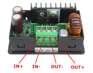
Although this guide is written for the ‘5005 it should work for the entire DPS family but I only have 5005s to test with. Before we begin I should mention that the stock firmware will be gone permanently. As readout protection is enabled on the STM32, the FW cannot be extracted and I have no source for it. Additionally, I take no responsibility if you destroy your DPS. That said, let the fun begin. You will need a DPS5005 (or similar), an STLink clone and some wire. Either you solder the wire onto the DPS or you can use female-male dupont wires for flashing.
Teardown
First you need to remove the PCB from the (semi) housing. Use a small flat screwdriver to prey the PCB loose from the retaining flaps.
Teardown
Be careful not to break the retaining flaps (not that they’re fragile, but still). They are very much needed for holding the front panel in place when you press the buttons.
If you have an older version (below left) you can solder some AWG26 wire onto the SWO and UART ports. It is advisable not to solder pin headers as there is limited room inside the housing. I added dupont jumper housings at the end of the cables to aid in connecting them to the STLink clone and FTDI ditto. Hint: make the cables “stretch” backwards, from the display. For newer versions (below right) the 1.25mm JST-GH there is little room for the SWD wires. As a bonus, you need not solder the UART cables in case you bought one of the “communications versions”.
Old SWO/UART pinout
New SWO pinout
If you do not want to solder (and do not want any remote control) (and have steady hands) you could connect three female-male dupont cables to the STLink clone and hold them pressed against the DPS while flashing.
Debugger connected, UART cable at the top
Building OpenDPS
With that in place you should install OpenOCD and an ARM GCC toolchain. For GCC, Launchpad is a good place to start. For OpenOCD, YMMW. If you are on macOS you can find OpenOCD here (it installs as /Applications/GNU ARM Eclipse/OpenOCD/0.10.0-201610281609-dev/bin/openocd). With the tools in place you’re ready for the next step.
git clone --recursive https://github.com/kanflo/opendps.git
cd opendps
make -C libopencm3
make -C opendps
make -C dpsboot
Flashing
Next you need to unlock the internal flash of the STM32 before flashing (which causes a complete erase). Start OpenOCD:
cd openocd/scripts
openocd -f interface/stlink-v2.cfg -f target/stm32f1x.cfg
You will receive a few lines of output ending with “Info : stm32f1x.cpu: hardware has 6 breakpoints, 4 watchpoints” if the connection was successful.
Please note! Before you unlock and erase the STM32 flash, you should make a dump of the STM32 peripheral settings of your stock DPS firmware. The DPS hardware might change at any time and if you flash OpenDPS and it does not work because eg. the GPIO pin enabling output power was changed, things get difficult. The ocd-client.py script will assist you now that OpenOCD is running. Please note that OpenOCD might interfere with the stock firmware. When you connect, the stock FW might lock up. First, power on the DPS and make sure the power output is disabled but set to e.g. 5V, start OpenOCD and type:
./ocd-client,py all > 5V-off.txt
If needed, restart the unit (and OpenOCD), enable power output @ 5V and type:
./ocd-client,py all > 5V-on.txt
Rinse and repeat for one or two more voltage levels. Check the log files, there should be no lines saying “Parsing error”. If your OpenDPS does not work, these files will enable me (or someone else, remember this is open source you 😀 ) to pinpoint the problem. Additionally,you should test the device before unlocking it. Enable power, connect something and verify that your unit actually works.
Now let’s wipe that flash. In another terminal:
telnet localhost 4444
and type:
reset halt
flash erase_address unlock 0x08000000 0x10000
You will probably get the following, ending with an error:
Device Security Bit Set
stm32f1x.cpu: target state: halted
target halted due to breakpoint, current mode: Thread
xPSR: 0x61000000 pc: 0x2000003a msp: 0x20000800
stm32x device protected
failed erasing sectors 0 to 63
Keep calm. Restart OpenOCD, toggle power on the DPS and try again. This time you should see:
erased address 0x08000000 (length 65536) in 0.094533s (677.012 KiB/s)
Time to flash (flash the app first, then the boot loader):
make -C opendps flash
make -C dpsboot flash
The last two lines should read:
** Verified OK **
** Resetting Target **
and your DPS5005 is now an OpenDPS 5005.
OpenDPS, now with wifi
Congratulations! If things went south somwhere, feel free to ask for help in the comments below.
From here you can use the OpenDPS as a stand alone device, control it via a serial port or control it via wifi by connecting an ESP8266.
Short User Manual
When you power on your OpenDPS, the current voltage and current limit settings are displayed and the power output is always disabled. Pressing ON/OFF will enable power output and the display will now show the measured output voltage and the measured current draw. If the screen flashes once and goes back to displaying the voltage/current settings, the over current protection kicked in. Press ON/OFF again to disable the power output.
Press the SET button to go into editing mode. Press the V and A buttons to move between the voltage and current settings. Press the rotary knob to step sideways and turn the knob to change the values. Press SET again to exit editing mode.
Press and hold the knob for two seconds to lock the keys, long press again to unlock. A long press of the SET key will invert the display.
When your OpenDPS starts it will wait for a wifi connection from a connected ESP8266 and the wifi icon will flash at 1Hz. If it does not get a wifi connection, the wifi icon will be turned off after 10 seconds. If there was an error connecting to your wifi network, the wifi icon will flash at 4Hz.
Remote Serial Control
If you soldered wires to the UART port, connect an FTDI adapter and try the dpsctl.py tool:
dpsctl.py -d /dev/tty.usb.yourdevice --ping
The TFT should flash once as a visual indication. If you get ‘Error: timeout talking to device’, check if you swapped RX and TX and/or forgot to connect GND.
The port setting can be set in an environment variable
export DPSIF=/dev/tty.usb.yourdevice
After setting the DPSIF variable, you can try setting the output voltage to 3.3V:
dpsctl.py --voltage 3300
enable the output:
dpsctl.py --power on
check the measurements:
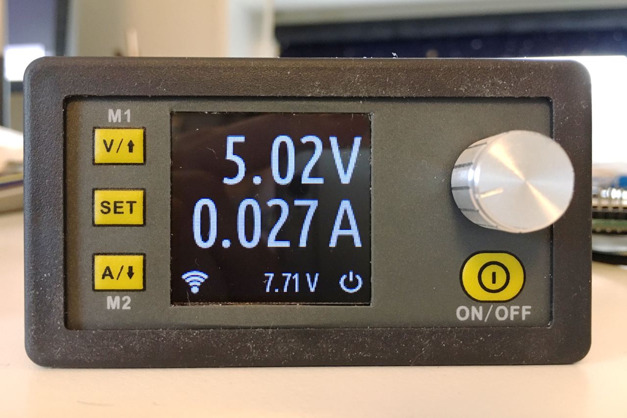
% dpsctl.py --status
V_in : 7.71 V
V_set : 3.30 V
V_out : 3.32 V (on)
I_lim : 0.100 A
I_out : 0.040 A
Run a firmware upgrade over the serial port (extra usable for newer versions where adding SWD is a hassle):
% make -C opendps bin
% dpsctl.py -d /dev/ttyUSB0 -U opendps/opendps.bin
If serial control is what you aimed for, you can get rid of the annoying flashing wifi icon by adding WIFI=0 when building OpenDPS
make clean ; make WIFI=0 flash
Remote Wifi Control
For wifi control, any good old ESP8266 board with the UART exposed will work. Connect GND, RX and TX, build and flash esp8266-proxy (don’t forget to set your wifi credentials) and you should be good to go.
git clone --recursive https://github.com/superhouse/esp-open-rtos.git
export EOR_ROOT=`pwd`/esp-open-rtos
echo '#define WIFI_SSID "my ssid"' > esp-open-rtos/include/private_ssid_config.h
echo '#define WIFI_PASS "my secret password"' >> esp-open-rtos/include/private_ssid_config.h
cd /path/to/esp8266-proxy
make && make flash
Note that you currently cannot use the master branch on the main ESP Open RTOS repository as my PR for a function needed for multicast has not been merged yet.
When your OpenDPS has connected to your wifi network, try the ‘scan’ command to find out its IP number:
% dpsctl.py --scan
172.16.3.203
1 OpenDPS device found
Next try pinging it:
% dpsctl.py -d 172.16.3.203 --ping
The TFT should flash once as a visual indication. If you get ‘Error: timeout talking to device 172.16.3.203’, check if you swapped RX and TX. The dpsctl.py tool has the same functionality over wifi as well as the serial port.
Sadly, you cannot power your ESP8266 from your OpenDPS. The VDD pin next to the SWO port is connected to U4 (under the TFT), an MD7133H 3.3V regulator which only provides a measly 30mA (yes, thirty). Additionally, this regulator is powered by U3 (on the backside, next to the screw terminal) which is an XL7005A supplying 400mA @ 5V which could be a bit over the edge for a power hungry, cold booting ESP8266.
Todos
There are a few todos in the code but overall OpenDPS should be stable for everyday use.
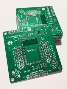
Sometimes you bet on the wrong horse. I put my money down on the ESP3212 as I had seen the images of sample modules and AiThinker seemed to be on the way to mass produce this lovely little thing. As I had a bunch of designs to send off to Dirty PCBs, I quickly whipped up an ESP3212 version of my Esparducam board. The day after the boards went into production (early november IIRC) I read that the ESP3212 was scrapped in favour of the ESP32S. Not a completely bad choice as the 3212 was not pin compatible with Espressifs version of the module. But still.
ESP3212 coaster 🙂
So, if you actually managed to get your hands on a ‘3212 and wish to test it on this board I’d be happy to send one to you for the price of p & p. Goodbye ESP3212, I hardly ever knew you.
People have asked if and when it would be possible to buy AAduinos. The answer to both questions is “sort of soonish” as I am about to start a crowd sourcing campaign with the good people over at Crowd Supply. Here’s their pre launch page. There are a number of cool projects running over there, Lime SDR is a personal favourite of mine.
Update Aug 28th: The BOM for all variants is now on Github. Please see the notes at the end if you want to build a Commadorable 64 yourself.
The ILI9341 based QVGA displays found on eBay for €4 are well suited for making small screenlets telling the current temperature, weather forecasts, traffic situation to work and spreading them over the house. As PCB design is both fun, cheap and rewarding I did a custom PCB for these tiny displays. Actually, I made three, one for each of the 2.2″, 2.4″ and 2.8″ screens. The 2.8″ version has not been produced but the smaller variant have and work well. From 2.4″ and onwards there is (untested) touch support on the screen modules.
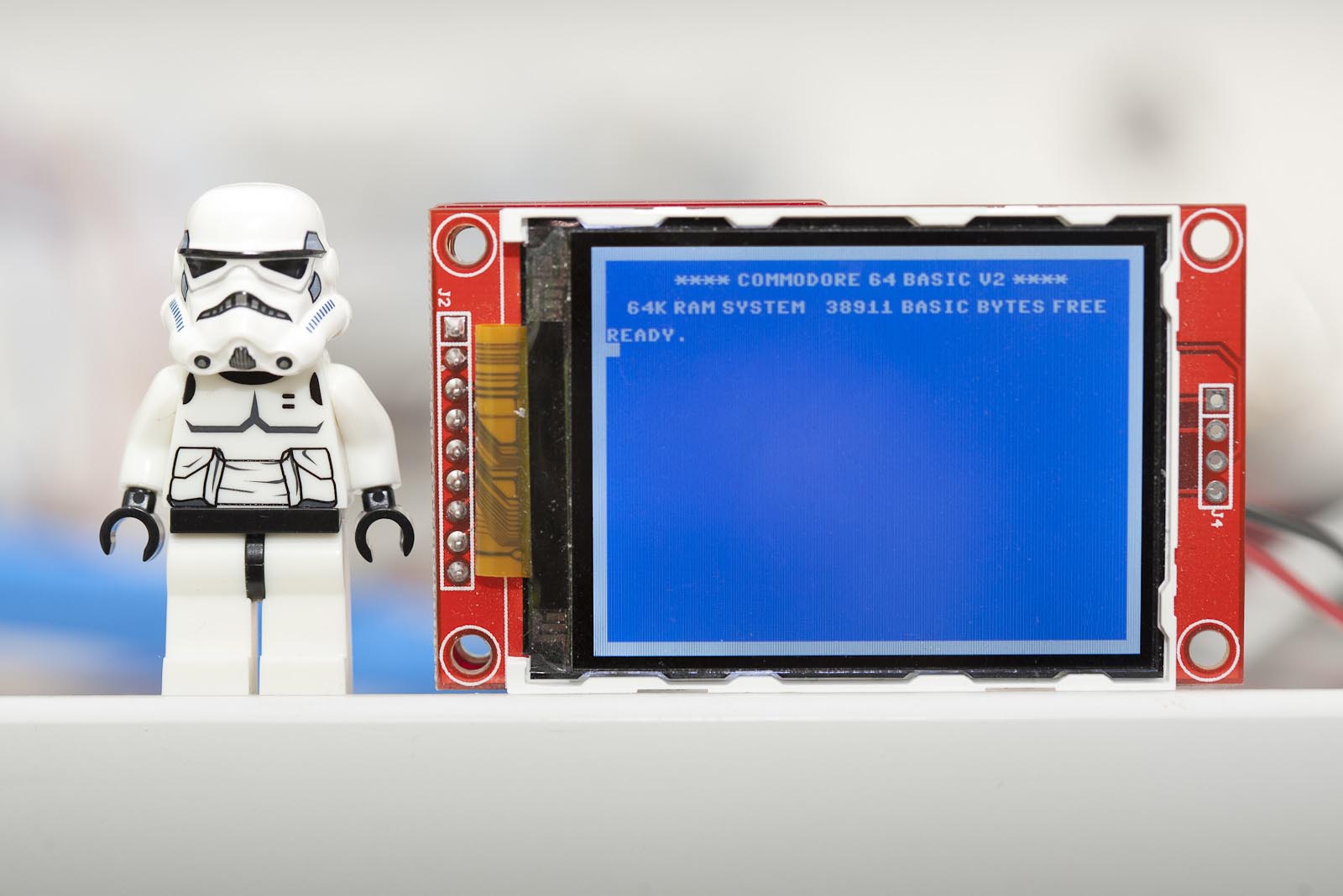
The “Hello World” application for this project also named the PCBs. I call them Commadorable 64. Here is why:
LEGO Stormtrooper added for size reference
The cursor blinks but I resisted the urge to create an animated GIF. “Commadorable 64” is a play with “Commodore 64” and “adorable”. It has been scientifically proven that those for whom the Commodore 64 played a significant part of their childhood will look at the 2.2″ version of the C64 start screen and react the same way as cat people looking at kittens. Heads will be tilted slightly sideways, smiles appear and sounds like “naaaaaaaw” will be heard. I have one of these at work and depending on childhood experiences people will either go “what?” or “naaaaaaw”.
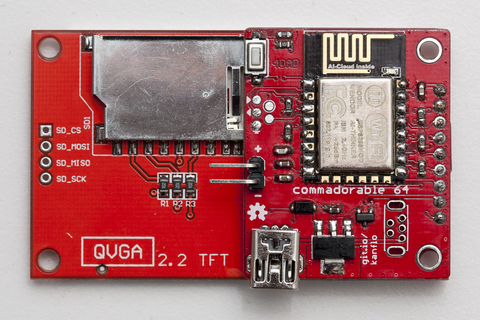
ESP side
The PCB is soldered directly to the pins of the ILI9341 module. Some of these screens will probably end up in other applications in the future. The other day I read about openframe.io and adding support for these would be fun.
The PCBs can be ordered from DirtyPCBs.com, 2.2″ with a bonus AAduino and 2.4″ version with touch. The BOM consists of the usual components for my ESP8266 designs. We have 0603 resistors and capacitors, a 3x6x2.5mm momentary push button [eBay] for displaying the IP address, a SOT23-3 P-mosfet to control the backlight, an LM1117 voltage regulator and a SOD-123FL schottky diode for reverse power protection and optional mini USB connectors. The PCB can be powered in three different ways depending on personal preference (well, four including the esprog interface). There are footprints for normal [eBay] and vertical [eBay] mini USB connectors, depending on if the module is to stand on a table or hang from a wall (Eagle parts available on Github). In addition there is a 0.1″ header for power. All power paths are protected by the diode.
2.2″ version without touch
2.4″ version with touch
Further update Aug 28th. I see some 20+ orders on DirtyPCBs for both Commadorable 64 variants which is great fun and I would really love to hear what you will build. I have some recommendations you might find useful. I have received a few broken ESP-12e/f modules on eBay over time and one broken ILI9341 module. Because of that I always try the modules before soldering them using my Esparducam board with the ESP Pinlet add on board. When a module passes testing I flash it with the ESP Open RTOS OTA basic demo meaning I can OTA any device directly after soldering. Also, you will note there is no FTDI connector on these boards, the reason is described here. As UART output is still useful, I have one “development” variant with leads from an FTDI connector soldered to the GND/RXI/TXO esprog pads. Oh, and I also have one Commadorable 64 board with a female header for testing the ILI9341 modules before soldering them. If you have any questions about building the boards, sound off in the comments below.
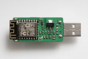
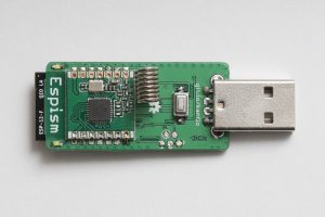
The ESP8266 has taken the maker community by storm and the hype is well deserved. Before the ESP we had the HopeRF ISM radio RFM12 and its successor RFM69. So is the ESP8266 an RFM69 killer? I would say no. Hell no even 🙂 The RFM69 is still very well suited for certain applications and the ESP8266 will not run for 2+ years on a set of AA batteries. The two can however play nicely together as a low cost ISM/wifi bridge. I did a custom PCB for this in the shape of a somewhat large USB stick, dubbed “Espism”.
Espism, ESP side
Espism, RFM side
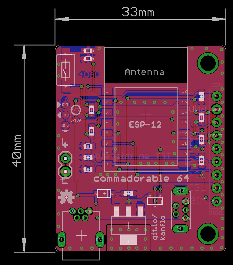
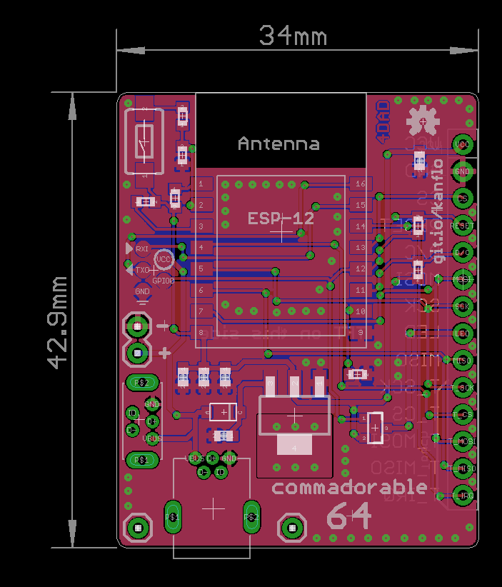
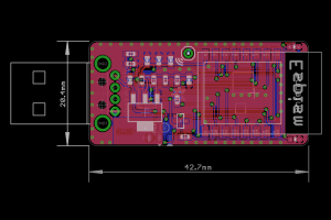
Espism, Eagle view
Currently it works as an ISM sniffer posting the received packets on the MQTT topic espism-<macaddr>. Packets are posted in hex followed by the RSSI value:
espism-5ccf7f147cd Hello from 172.16.3.120
espism-5ccf7f147cd 016340630001000000c375b642[-27]
espism-5ccf7f147cd 630180[-57]
A set of four LEDs indicate received packets. Well three LEDs as I made a mistake on the ground plane. The MQTT server IP and RFM69 network information is hard coded into the binary.
I ported Andreas Heßling’s STM32 RFM driver to the lovely ESP Open RTOS, my swiss army knife for ESP8266 development. The type-A right angle 90 degreee USB connector and 3x6x2.5mm push button can be found for little money on eBay. The push button currently serves no purpose but the plan is to perform a “master reset” of the device using this button. The rest of the BOM consists of 0603 resistors and capacitors, an LM1117 3.3V regulator and a SOT23 P-mosfet for driving the 0603 LEDs. Oh, and the ESP12F talking to an RFM69CW. The BOM should add up to about the price of lunch.
This is a standard WordPress installation that most likely uses cookies. Frankly, I haven't checked but recall being obliged to tell you under EU law so here goes: This site uses cookies. Things will probably not go south if you turn them off. Either way, I am into building stuff and not tracking people nor selling advertising space so you can feel safe here.