The FTDI connector can be found on just about any ESP8266 design. If you are building a gadget to be deployed somewhere and not a full blown development board, the FTDI connector is somewhat overkill. And it is quite large. A few pins could be shaved off but we still have a through hole connector invading the other side of the PCB.
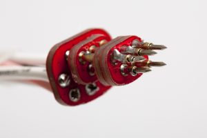
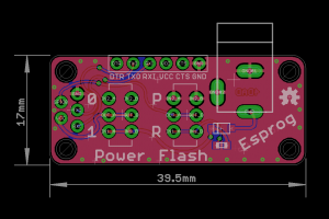
I ended up designing my own connector and it has been used sucessfully in all of my recent projects. The connector consists of five test points providing power, GND, TXO, RXI and GPIO0 for boot control. It takes very little single sided PCB space and is inspired by the TagConnect I use at work. Note that the power provided through the connector is unregulated.
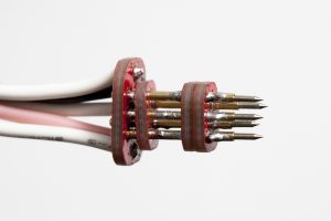
Esprog pogo pin connector
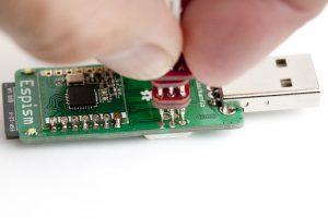
Gadget programming
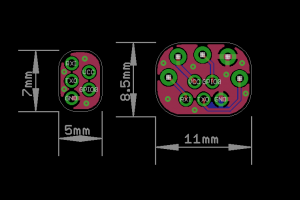
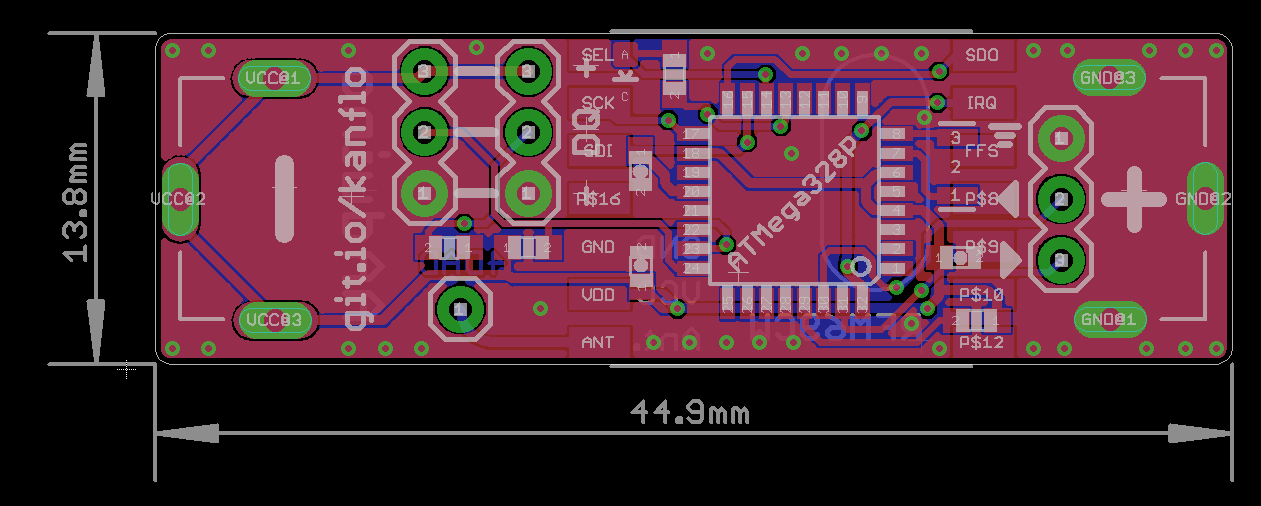
Adapter, Eagle view
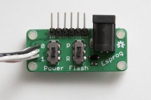
I also designed a pogo pin connector to mate the test points and a small board with a DC barrel connector and the FTDI connector. This board has two switches for power and boot mode selection.
If you look carefully on the pogo pin adapter you see that the power pin is somewhat retracted. As the adapter will be hand held, the four other pins can be aligned to the device and with a gentle push power will be applied.
News: the crowd sourcing campaign for the AAduino will start soon, sign up at CrowdSupply to be notified! The specs have been beefed with an STM32L0 cpu and the temperature sensor is now an industrial grade TMP102.
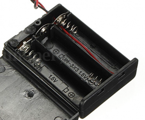
I have been using Nathan Chantrell’s Tiny328 for quite some time as my swiss army knife ISM radio node. Now I wanted a more slim ISM node as my setup with a Tiny328 on a breadboard is not very “deployable”. I could of course 3D print a case for the Tiny328 but I have limited access to 3D printers and do not feel I have the time to explore that exciting part of the maker world just yet. This leaves me with finding off the shelf project boxes with a compartment for 2x AA batteries and the “radioduino” (and in an acceptable form factor). That search came up disappointingly, and surprisingly, short. I did have a set of standard eBay AA battery holders and looking at the 3x variant it occured to me. I needed to shrink the radio node, and the AAduino was born.
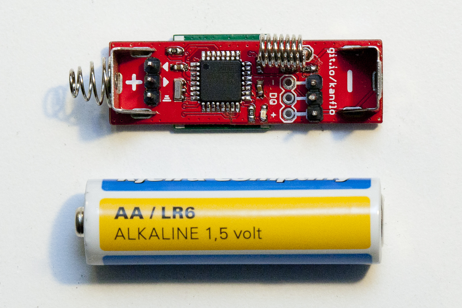
Honey, I shrunk the radioduino!
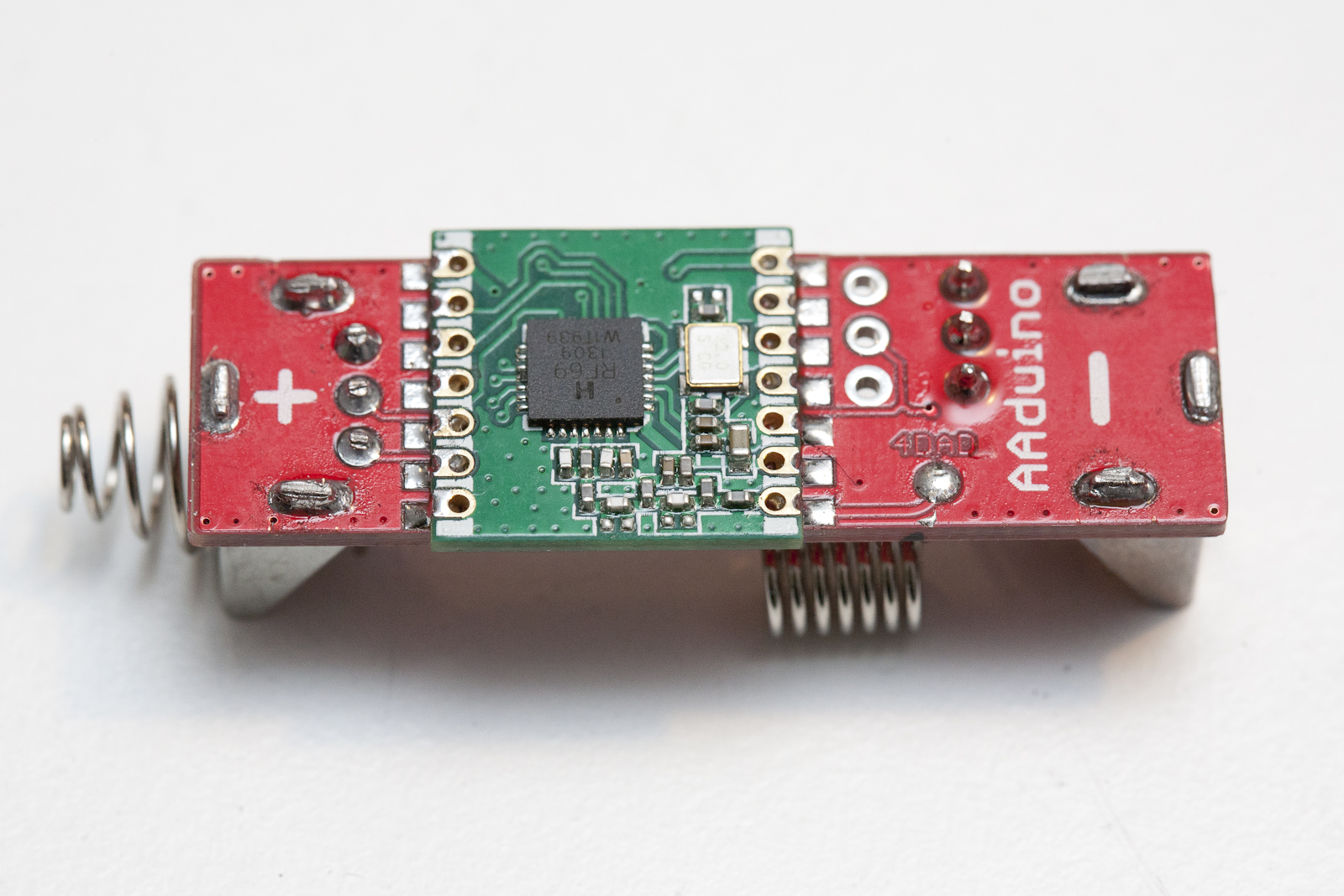
The AAduino is an wireless Arduino clone the size of an AA battery with Keystone battery terminals rotated 180° to act as positive and negative terminals. It is powered by an ATMega328p and is fitted with an RFM69C companion. There is room for two DS18B20 temperature sensors and an indicator LED.
I still think it looks a bit weird 🙂
It runs at 8Mhz to allow for greater life span since the CPU can run at a lower voltage. I have fused the 328 to brown out at 1.7V which is a bit out of spec at 8Mhz and slightly below what the RFM69C needs. Running at 4Mhz would be more suitable but I will see how well the node performs when the batteries are draining out.
AAduino, RFM69C side
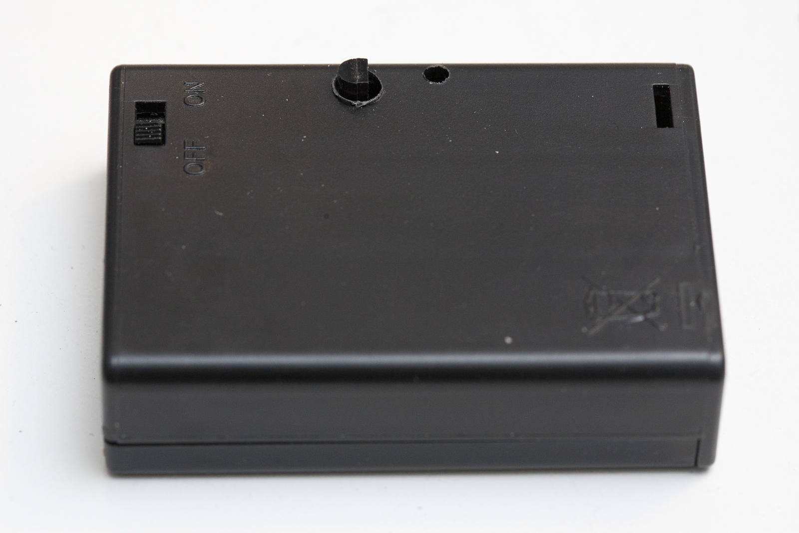
Since the RFM69C is somewhat wider than an AA battery I used a file to make it slightly narrower. There is some room for that kind of modification without damaging the module. Update, the RFM69C will fit without modification. Next I clipped the legs of the DS18B20 until about 5mm remained and soldered it to the 3x pin header on the AAduino. I then drilled a hole in the battery box where the sensor can protrude and a small hole for the LED to shine through. The wire out of the battery box was cut, shorted and stuffed away inside the box.
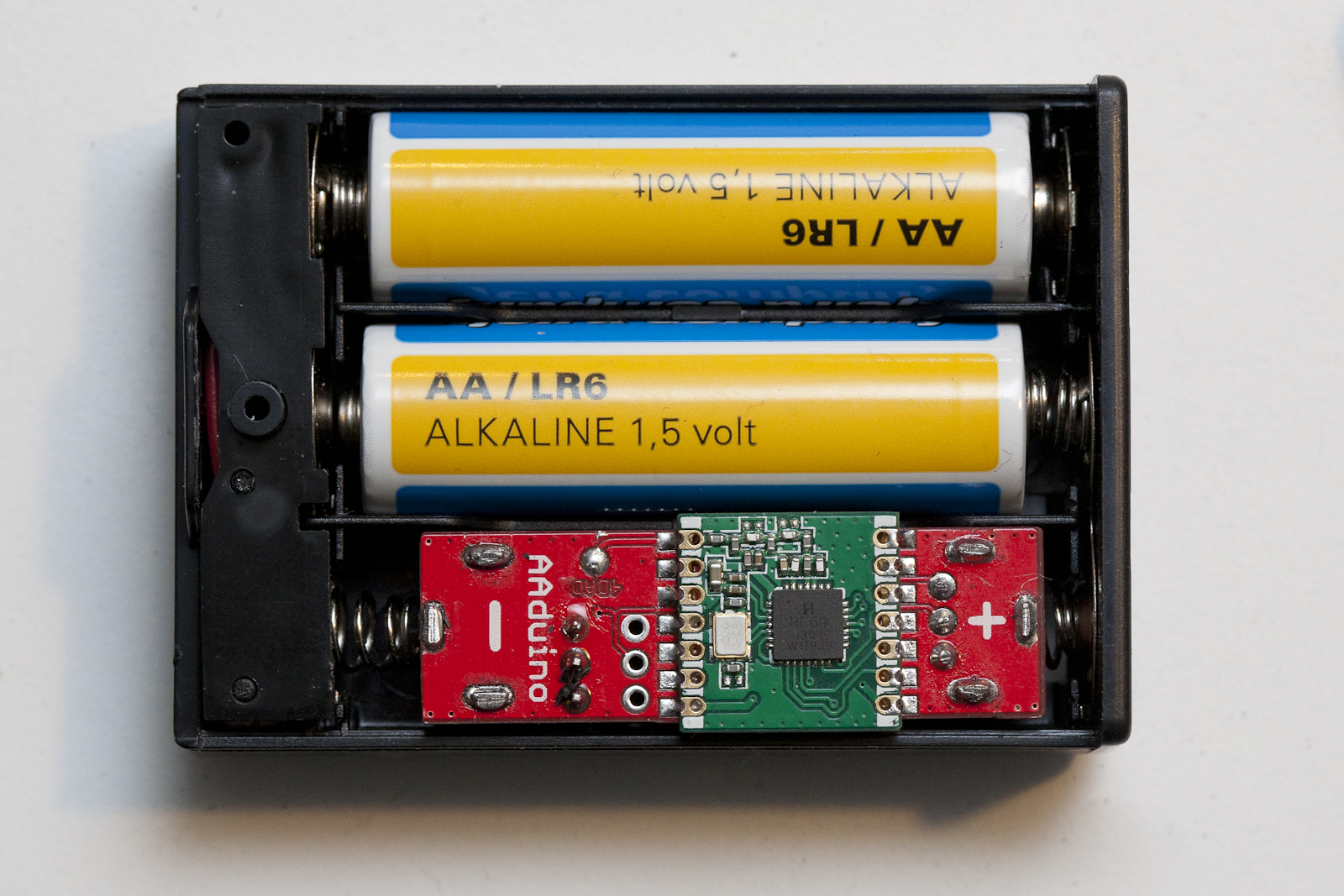
AAduino inside 3xAA box
I use battery terminals from Keystone available from RS Components, positive and negative. There seems to be a cheap eBay alternative but I have not tested those. The + and – markings on the PCB indicates (this is important, read carefully) the positive and negative poles of the battery we are pretending the AAduino is. The Keystone spring contact should be soldered to the + marking and the button contact to the – marking. There is no protection diode here so be careful. Also note! If you want to power the AAduino from a bench power supply, connect the power supply’s black negative lead to the + marking and the red positive lead to the – marking.
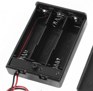
The 3xAA boxes are also from eBay and there seem to be two different types. One that is really good and one that is really crappy. I will let you in on the secret of buying the correct one. The good ones have a nice build quality and plastics and look like this. Note the rectangular piece of plastic below the battery compartment extending from side to side.
Good 3xAA holder
Looking at the crappy ones, well you can tell can’t you? In the top left corner it seems someone used a soldering iron on the poor thing. The lid does not snap in place very well and the plastics is really cheap.
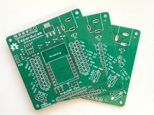
I have had some questions about the possibility to purchase Esparducam boards and also about the bill of material. While I am looking into selling spare boards, here are some instructions about building the boards. Here is the link to order the PCBs [dirtypcbs.com].
If you have never tried building surface mounted boards yourself I highly recommend you try it! I started here [nathan.chantrell.net] and googled my way from there.
The following parts are optional depending on what you want to do with your board:
Reverse current protection
D1 SOD-123FL, schottky diode for reverse current protection [eBay],
If you feel brave you can bypass the diode by placing a blob of solder across SJ2 on the back of the board.
Adding motion detection
If you want to attach a PIR [eBay] you need:
J2 JST ZH connector, 3 pin [eBay]
R6 220k 0603
R7 100k 0603
R6 and R7 was going to be a voltage divider that I messed up leaving R7 optional. Please note that the PIR does not work at 3.3V. To bypass this without adding a 5V regulator I simply feed the PIR with the raw board voltage which in my case is 5V.
Controlling power to the Arducam Mini
If you want to be able to control the power to the Arducam Mini board you need Q2 and R5. If you feel ok to have power constantly enabled simple place a blob of solder across SJ1 at the back of the board.
Q2 P mosfet, SOT-23 [eBay]
R5 4k7 0605
External flash
The external SPI flash is also optional. Please note that the footprint is somewhat too narrow, some flashes might not fit.
U2 SPI flash SOIC-8
C5 0.1uF 0603
Adding header pins
These optional headers are for attaching add-on boards or pins for taking measurements
JP3, JP6 8 pin 2.54mm male header
JP4,JP5 8 pin 2.54mm female header
That’s it, good luck!
Loading Comments...
This is a standard WordPress installation that most likely uses cookies. Frankly, I haven't checked but recall being obliged to tell you under EU law so here goes: This site uses cookies. Things will probably not go south if you turn them off. Either way, I am into building stuff and not tracking people nor selling advertising space so you can feel safe here.