Is the wash done?

Checking if the washing machine is done is a popular (not to mention useful) application. This is often done by sticking LDRs to the washing machine, adding IMU sensors or analyzing mains power usage or even the sound emitted.

I needed a solution with minimal time effort as I have lots of other things I want to do so I went with a Raspberry Pi Zero W and a PiCamera. Starting as “wash monitor” it transformed to “appliance monitor” as any appliance can be monitored. I have a single Raspberry Pi keeping an eye on both the washing machine and the tumble dryer.

The idea is simple, take a picture, process and count pixels:

  • All black: lights are off and the machine is off
  • Most black: lights are off and the machine is on
  • Few black: lights are on, machine state is unknown

Next, the “lights” and “machine” states are tracked and a notification is sent when “machine” goes from “on” to “off”. Pushover is used as notification service and MQTT for general service monitoring.

There are a few prerequisites that make this solution actually work (yes I know you objected to the idea):

  1. My washing machine is in the basement, ie. in a “controlled light environment”.
  2. The lights in the laundry room are Ikea Trådfri ones activated by a motion sensor and they switch off after a few minutes meaning we will never be stuck in the “lights are on, machine state unknown” state.
  3. Normally no-one enters the laundry room minimising the risk of false positives by a person dressed in black pants standing in front of the camera.

The system works great for me but might be completely useless to you 😀

MJPEG Streamer is used for snapping pictures and ImageMagick for processing. Pictures are cropped to only reveal the display which increases the percentage of non black pixels when the machine is on. Blurring is used to increase specular highlight of the LEDs, a threshold filter is applied making sure we end up with only black and white pixels (and no image sensor noise) and finally the histogram is calculated. The Pi is taped to the wall opposite the machines so it will not move (which would mess up the cropping).

Here is an unprocessed cropped picture of the washing machine display when the room is lit:
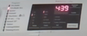
0% completely black pixels

(Applying blur and threshold filters now yields a completely white picture from which we can only determine the lights are on)

The same picture with the lights off:
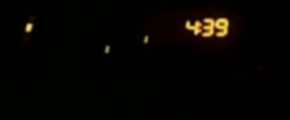
Blur and threshold filters applied:

~84% completely black pixels

Lights off, machine off, blur and threshold filters applied:

100% completely black pixels

Installing and configuring

First clone this the Appliance Monitor repo:

git clone https://github.com/kanflo/appliancemon

You need ImageMagick, Python Requests and Paho MQTT and MJPG Streamer (and of course lots of stuff to be able to build):

sudo apt-get install imagemagick
sudo apt-get install python3-pip
sudo pip3 install paho-mqtt requests
sudo apt-get install build-essential git libjpeg8-dev imagemagick libv4l-dev cmake
git clone https://github.com/jacksonliam/mjpg-streamer.git
cd mjpg-streamer/mjpg-streamer-experimental
make && sudo make install

To spare the poor MicroSD card I use a RAM disk for image processing and a script is provided that adds the RAM disk to /etc/fstab:

sudo ./create-ramdisk.sh

Next, copy sampleconfig.yml and modify as needed (there are lots of comments to guide you). The “image processing parameters” section can be skipped for now.

A start script for MJPG Streamer is included where parameters such as white balance can be set:

sudo /home/pi/appliancemon/mjpg-streamer.sh start

If this fails, check the bcm2835 Video4Linux driver module is loaded and then try to start MJPG Streamer again:

sudo modprobe bcm2835-v4l2

To make it load on boot:

sudo echo "bcm2835-v4l2" >> /etc/modules

Snap a picture:

curl -so image.jpg "http://wash.local:8080/?action=snapshot.png"

Use this image to determine the crop area specified in ImageMagick style (blur and threshold are also IM style, check the ImageMagick documentation for help).

Now try the cropping and calculate the black level. The last two zeroes are “blur” and “threshold” (zero means disable).

./applimon.py -c washconfig.yml -t "290x120+20+410 0 0" ; open image-proc-washer.png
Black level: 0%

Now turn on the machine, turn off the lights and apply blur and threshold:

./applimon.py -c washconfig.yml -t "290x120+20+410 0x6 6"
Black level: 94%

And finally turn the machine off:

./applimon.py -c washconfig.yml -t "290x120+20+410 0x6 6"
Black level: 100%

You may need to elaborate with the blur and threshold parameters to get satisfactory black levels. I use the ones in the sample config for both my washing machine and tumble dryer.

Finally add the following lines to crontab -e:

@reboot /home/pi/appliancemon/mjpg-streamer.sh start
@reboot /home/pi/appliancemon/applimon.py -c /home/pi/washconfig.yml &
@reboot /home/pi/appliancemon/applimon.py -c /home/pi/dryerconfig.yml &

Code on GitHub as always.
Bridging ISM radio and wifi for lunch money

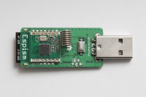
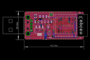
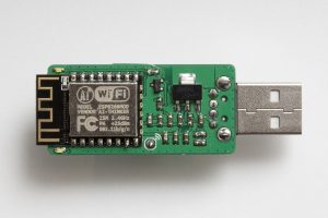
The ESP8266 has taken the maker community by storm and the hype is well deserved. Before the ESP we had the HopeRF ISM radio RFM12 and its successor RFM69. So is the ESP8266 an RFM69 killer? I would say no. Hell no even 🙂 The RFM69 is still very well suited for certain applications and the ESP8266 will not run for 2+ years on a set of AA batteries. The two can however play nicely together as a low cost ISM/wifi bridge. I did a custom PCB for this in the shape of a somewhat large USB stick, dubbed “Espism”.


Currently it works as an ISM sniffer posting the received packets on the MQTT topic espism-<macaddr>. Packets are posted in hex followed by the RSSI value:

espism-5ccf7f147cd Hello from 172.16.3.120
espism-5ccf7f147cd 016340630001000000c375b642[-27]
espism-5ccf7f147cd 630180[-57]

A set of four LEDs indicate received packets. Well three LEDs as I made a mistake on the ground plane. The MQTT server IP and RFM69 network information is hard coded into the binary.

I ported Andreas Heßling’s STM32 RFM driver to the lovely ESP Open RTOS, my swiss army knife for ESP8266 development. The type-A right angle 90 degreee USB connector and 3x6x2.5mm push button can be found for little money on eBay. The push button currently serves no purpose but the plan is to perform a “master reset” of the device using this button. The rest of the BOM consists of 0603 resistors and capacitors, an LM1117 3.3V regulator and a SOT23 P-mosfet for driving the 0603 LEDs. Oh, and the ESP12F talking to an RFM69CW. The BOM should add up to about the price of lunch.

Code and schematics on Github as always.

Commercial pilots control my moodlight

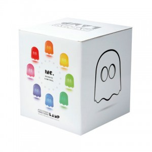
Having spent some time building the Wifi Ghost I wanted it to be something that was actually used. Few people in the house found the interest to change color on a daily basis (myself included). Then it occured to me, why not let the pilots of the aircrafts buzzing around the airspace of southern Sweden control it? They will probably never know that by passing within a few kilometers of my ADS-B receiver they will light up my study.

This will be a small project as most parts are already in place. The ADS-B tracker from my Skygrazer project will feed a script that sets the ghost color via its MQTT topic. What color though? Well, the most prominent color in the airlines’s logo of course! Make a Bing image search for the name of the airline with the word “logo” appended, pick an image, download and analyze. The color will be dimmed according to the distance to the aircraft. I use a maximum distance of 2 kilometers making the light fade up and down whenever an aircraft passes near my house.

The result? A wifi ghost light put to good use. And art 🙂

Code available on Github.

ADS-B skygrazing

This is a followup to my previous post about bringing life back to an old Macintosh Classic II.

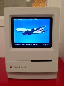
Having an iconic Mac with a Raspberry Pi inside doing nothing is kind of dull. I wanted the Classic to display something interesting (at least in my point of view) and I did have another Raspberry Pi in the attic receiving ADS-B data and posting to an MQTT feed. How about showing a picture of the nearest aircraft with information about its speed, heading, altitude, distance, bearing and so on?

Without diving too much into the details about ADS-B, what we get from the aircraft is basically speed, heading, altitude and a 24 bit identification number, the icao24. This is a globally unique aircraft ID registered with the International Civil Aviation Organization and we somehow need to convert this into an actual image of the aircraft.

The aircraft’s operator, type and registration are not available in the ADS-B data the aircraft transmits and needs to be pulled from another data source. One excellent source is PlaneBaseNG with about 147k aircrafts. The database consists of an SQLite database which serves us well. Once we have the aircraft type and operator we make a Bing image search and pull an image of suitable size.

The system architecture looks like this, with data flowing from top to bottom

ADS-B receiver
ADS-B client
Proximity radar
Skygrazer

The ADS-B receiver is a Raspberry Pi with an RTL dongle running dump1090.

ADS-B client is a Python script parsing data from dump1090’s feed on port 30003, converting it into a JSON object, adding aircraft data from PlaneBase and publishing on the MQTT topic “`/adsb/radar/json“`.

Proximity radar is another Python script subscribing to “`adsb/json“` while keeping track of which aircraft is the closest one. It calculates distance and bearing, performs image lookup and publishes on the MQTT topic “`adsb/proximity/json“`.

Skygrazer is an application written in SDL2 subscribing to the topic “`adsb/proximity/json“` that downloads and displays the image and flight data received.

The architecture might seem like an overkill but I like the publish/subscribe idea of MQTT, it is a bit like Unix commands. Each one performing one task (and performing it well) and several commands may be chained to create something bigger that the sum of its parts. It also lends itself well to other ideas I have of how to have fun with ADS-B data.

Here is an image of the Classic in action with an A380 from Emirates passing by.

A380 Classic
Airbus A380 image from Wikipedia, Quentin Douchet CC BY-SA 3.0

The project turned out nicely. The Classic runs 24/7 and since the airspace over the southern tip of Sweden is quite busy there is always something going on. I have almost gotten to know some of the aircrafts and flights around here. A quick glance on the Classic and I can tell I am looking at the Air France A380 from Charles de Gaulle to Tokyo. Nerdy huh?

Update! Checkout further use of the ADS-B data in “Commercial pilots control my moonlight“.

Code available here and here on Github.

Serializing data from IoT nodes

This is a followup to my previous post about my home automation/IoT system. I introduced some of the hardware used to build sensors and now I will look at an architecture for sending data from sensor nodes to a receiver. First I will explain the initial attempt at sending data from nodes and why that was destined to fail. Next we will look at an architecture for data serialization and quick node prototyping.


Doomed for failure

The first attempt at sending data was quite simplistic with data structures being sent through the air. The base structure looked like this:

typedef struct {
 unsigned char type;
 unsigned char seq_no;
} branly_report_t;

From this struct, holding a message type and a sequence number, I defined others for different kinds of sensor data, eg. temperature:

typedef struct {
 branly_report_t br;
 int temp;
} temp_report_t;

sensor battery voltage:

typedef struct {
 branly_report_t br;
 unsigned char vcc;
} battery_report_t;

plant moisture:

typedef struct {
 branly_report_t br;
 int temperature;
 unsigned int moisture;
 unsigned char alarm;
} plant_report_t;

and so on. Whenever I thought of a new kind of node I would implement a data structure for the data being transmitted. The receiver would look at the sequence number to skip duplicate transmissions and, most importantly, the type field to know what kind of data was being sent.


This is a horrible way of doing things.


Each new node type being built would require a copy paste job on both the node side (copy a previous implementation and make changes) and one on the receiver side (again, copy previous implementation and make changes). The receiver would of course require knowledge of all different branly_report_t types.

An actual architecture

The solution? Data serialization. Taking a step back makes one realize that we have do not want system with nodes reporting temperature, other nodes reporting plant moisture and so on. We want a system with nodes transmitting data. There is quite a difference between the two you see. Frankly we do not even care what kind of data nodes transmit until we want to act on it or look at it. Discussing this problem with a colleague I came up with the following model of nodes and contacts.

  1. A node has an identification number and one or more contacts.
  2. Each contact has an index number, 0..N.
  3. A contact has a predefined type that everybody agrees on.
  4. A contact may define a fixed reporting interval.
  5. A contact is readable and possibly writable.
  6. A contact may be violated, eg. a battery contact is violated if the battery voltage drops below a defined limit.

Any transmission from the node would be a reduced to a message with an updated contact property (contact identification number, contact value and flags for violations). A writable contact (eg. an RGB light) would receive messages with the same kind of data. Lots and lots of contact types can be defined and adding more further down the road is not as much of a hassle as the copy-and-past jobs mentioned earlier. Even more important, a node can report any data we want it to. My garage node could report inside and outside temperatures as well as the light intensity level (needed to know if I forgot to turn off the lights at night) without me cooking up some strange data structure only implemented once in one single node.

An example node

Before diving into how this idea of data serialization is implemented, let us look at an example. The Arduino node sketch below uses the RFM69 ISM radio to send data and has two contacts; battery voltage (reported every 1h 30min) and temperature (reported every 15min).

// Contact value getters
long temperatureValue(bool setValue, long value);
long batteryValue(bool setValue, long value);

RFM69 radio;
BranlyNode node(&radio, HW_VERSION, SW_VERSION);
BranlyContact battery(1, kTypeVoltage, batteryValue, k1Hour+2*k15Minutes);
BranlyContact temperature(2, kTypeTemperature, temperatureValue, k15Minutes);

long batteryValue(bool setValue, long value)
{
 (void) setValue; (void) value; // Contact is not writeable
 return 2940; // Sample data
}

long temperatureValue(bool setValue, long value)
{
 (void) setValue; (void) value; // Contact is not writeable
 return 245; // Fixedpoint, 24.5deg (sample data)
}

void setup()
{
 radio.initialize(NODE_FREQ, NWK_ID, NODE_ID);
 radio.sleep();
 radio.encrypt(CRYPT_KEY);
 battery.setLowerThreshold(2400); // Contact violated if VCC drops below 2.4V
}

void loop()
{
 node.run();
}

Yup, it does not take more code than that to create the full node software stack. Define the node, its contacts with contact getters (and setters if contact is writeable), define reporting intervals and call node.run();

Nodes

A node has, besides its contacts, version fields for hardware and software and an internal state (refer to BranlyNode.cpp). Upon boot the node step though its mCurState state variable until it has synchronized with the receiver. It will go through the following steps, requiring an ACK from the receiver in each step:

  1. send a ping packet and wait for a response from the receiver.
  2. send a hello packet with HW/SW versions.
  3. send a complete list of its contacts.
  4. send a complete contact report.
  5. wait until the next reporting interval and send a report on that specific contact

The receiver requires no configuration in order to receive data from a node. Instead, the node will tell the receiver what kind of data it will transmit.

Contacts

A contact (see BranlyContact.cpp) has an index and type as mentioned as well as a getter function and optional reporting interval. Contacts may be “enqueued” meaning its report will be transmitted on the next call to node.run. A button contact will typically be enqueued from an interrupt handler.

The radio protocol

The radio protocol has beed designed to be minimalistic to save power (critics may say the ping packet is not strictly necessary) and the heavy lifting is done in BranlyProtocol.cpp.

Each contact in the contact list (see buildContactListPacket) occupies a single byte, 1 bit for writeable, 3 bits for index and 4 bits for type (currently limiting the number of contacts to 8 per node and contact types to 16 in all, probably needs to be increased).

In the contact report (see buildContactReportPacket), contacts are encoded in 2-5 bytes with a flag field (for tracking violations), a size field telling how many bytes are needed to encode the current contact value and the actual value (1-4 bytes).

Lastly, contact value reports (see buildContactValuePacket) also uses 2-5 bytes and are sent in the same manner as contact reports.

The receiver

The receiver reads frames tom the BranlyPi modem running this receiver sketch. On the host side, the receiver is written in python and posts the received data to an Emoncms installation. The beauty of it all is that the receiver can create the Emoncms feed for each contact for a node on the fly based on the contact list packet.


Closing remarks

The current architecture has really enabled me to quickly prototype new nodes without changing a single line of code in the receiver and very few lines of code are needed to create a new RF node. On the receiver side, names need to be added for nodes and contacts enabling automatic bridging between RF node updates and, say, MQTT. Martin Harizanov is working on something similar and it will be exciting to see what he has come up with. If you know other implementations on this topic, please let me know in the comments below.


My wifi ghost lamp

Sometime ago all wifi hobbyist projects where quite expensive. USB Wifi dongles could be found for a handfull or dollars apiece but something easily connectible to a micro controller was also “connected” with a hefty price tag. Then the ESP8266 surfaced…

Having just purchased a Pac Man ghost LED lamp on the Black Friday sale I quickly saw an application for the ESP8266. Nothing novel, nothing that hadn’t been done 100 times before but something fun.


Make the ghost green
A warranty waiting to be voided

The software part

Following in the MQTT footsteps of previous projects I decided against running a server on the ESP8266 listening to yet another protocol implementation. Instead the ghost would listen to an MQTT topic and light up accordingly. I also wanted it to be able to run preconfigured light shows. The ESP8266 runs tuanpmt’s MQTT implementation and listens to the topic ghost/led sending anything it receives to the Arduino which responds to the following commands:

  • #RRGGBB – set all LEDs to specified color
  • :nnRRGGBB – set LED nn to specified color
  • – update the LED ring with all LEDs set with the :nnRRGGBB commands
  • p01 – run “light show” 01
  • * – turn all LEDs off

The “anything it receives” means I can add functionbality on the Arduino without touching the firmware on the ESP8266.

The hardware part

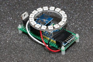
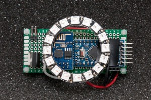
The hardware consists of the following:

  • ESP8266-01 board
  • Arduino Nano
  • 16 LED Neopixel Ring
  • Level shifter
  • 3.3V regulator with buddy capacitors
  • 1A USB charger

I purchased an Adafruit Neopixel ring with the lovely WS2812 LEDs. To save some time I took an Arduino I had lying around to control the LEDs using the Adafruit library. The two systems talks over UART. The Arduino runs at 5V (the level at which it can control the Neopixel ring) and the ESP8266 run at 3.3V which means a level shifter needs to be placed between the two. You can find level shifters almost for free on eBay. The wiring is quite simple. The USB charger provides 5V for the Arduino, the Neopixel ring and the high side side of the level shifter. The regulator provides 3.3V for the ESP8266 and the low side of the level shifter. I threw everything together on a prototyping board, nothing will be visibe anyhow 🙂

Once wired up the ghost can be tested with the command

% mosquitto_pub -t "ghost/led" -m "#00ff00"

The hard part

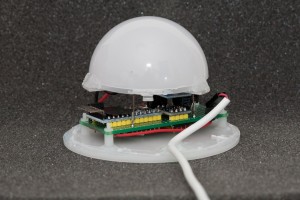
The board sits on nylon spacers to be glued to the lamp base

Now for the hard part, mounting the hardware inside the ghost. The ghost case is made up of three parts. The dome, the base and a bottom plate where the electronics is attached. The bottom plate is attached to the base using screws and the base is glued to the dome. This leaves the screws on the inside meaning the ghost cannot be cracked open without causing permanent damage. Using a fine saw and a drill I removed the bottom plate, sanded the edges and rinsed the dome in water ro remove the plastic dust. The electronics is mounted on spacers on the bottom plate and I used silicone to reattach it to the dome. It stays in place and reopening should not be that hard.

More software

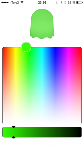
Controlling the ghost via the command line would not attract much venture capital so I set out to make an iPhone app for controlling the ghost. NKOColorPickerView and MQTTKit fit the bill and resulted in this neat little app I installed on my son’s iPad.

Make the ghost green

He was somewhat impressed and have changed the ghost color about three times to date which was in line with my expectations. I do have other plans for the wifi ghost, but that’s for another post.

Code available on Github

Final thoughts

In the time between finishing this hack and actually writing about it, Arduino on the ESP8266 has matured phenomenally so today I would skip the AVR. Actually I could replace all the hardware with the WifiPixels.

Gallery

A wifi OLED display for my wife

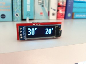
Somehow, the cord to the external temperature probe got ripped the out of the temperature display in the bedroom. My wife insisted on us purchasing a new thermometer but as an engineer I immedietaly saw the opportunity to build hardware and write software. Spending lots of time and resources on “engineering joy” is not something one can do at work but in one’s sparetime the sky is (almost) the limit.

So instead of spending about a dozen Euros on a new thermometer I designed and built a PCB and wrote code which was a lot more fun and educational. And way more expensive 🙂 The result is the Wife OLED that displays the current outside temperature as well as the forecasted temperature in 8 hours. While the morning might be cold, it is nice to know what the temperature will be at lunchtime.

WifeOLED
Another ESP8266 MQTT OLED display, on the warmest day this summer!

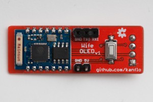
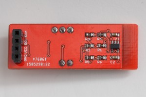
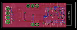
As the OLED display would be always on and close to a power outlet I choose a wifi solution and went for the the ESP8266, more specifically the ESP-03 module for its small size. The OLED was found on eBay, is a mere 0.91″ large and has an active area of 128×32 pixels. The device runs from a USB charger and an SPX3819 LDO provides the 3.3V the ESP and OLED needs. I designed a PCB in Eagle and had DirtyPBCs.com produce it. As the PCB is quite constrained on size there is no full FTDI-style connector. The RX/TX pins and ground are the only ones available for programming and a small tactile switch is used to get the ESP8266 into download mode.l

Looking at the software side, it turned out most of the work had been done by Nathan Chantrell (and others). He used a 128×64 pixel OLED display and the driver seemed to originate from the Arduino OLED driver by Adafruit. As I had chosen a 128×32 pixel display the driver needed some work. Also the available fonts where too small to be readable from across the room so I rendered Ubuntu Condensed in 28px and 32px. The larger font will be used for displaying the current temperature and the smaller one for the forecasted temperature. The device subscribes to the MQTT topics `home/temperature/outside` and `home/temperature/forecast` and displays whatever arrives on those topics.

The current outside temperature comes from my setup with a Tiny328 node equipped with a DS18B20 probe and a Raspberry Pi gateway (a future post). The forecasted temperature is pulled from the open data feed of the Swedish Meteorological and Hydrological Institute (SMHI) using the script get-weather-smhi.py.

The HW schematics (and gerbers!) as well as the SW is found on GitHub.

A note one year later: The OLED display will start to deteriorate after about half a year. It will still be readable but the pixels get “worn out” and will not be as bright. I would not recommend soldering the display to the PCB for this reason. Nowadays these displays retail at €2.50 on eBay so a replacement now and then is acceptable.