This is the second part about hacking the DPS5005. Part one covers the reverse engineering of the DPS5005 and part three covers the process of upgrading stock DPS5005:s to OpenDPS.
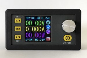
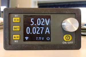
The goal of OpenDPS is to reflash the stock DPS5005 (and friends) with a firmware that has the same functionality, has a less cluttered user interface and is remote controllable via wifi or a serial port. The application needs to respond to user input both via buttons and the serial port and also via ADC readings telling us if the current draw is larger than what we allowed. Buttons and UART RX are handled using interrupts and obviously the ADC needs to be interrupt based too for fast response (and less smoke). Responding to user input and TFT drawing can be left to the application context.
System Overview
The following modules are used in OpenDPS:
- event – uses a ring buffer for storing events from the interrupt context to be handled in the application context. Events are button presses, received bytes on the UART and over current protection triggers
- hw – the hardware abstraction (ADC, GPIO, …)
- ili9631c – the TFT driver
- opendps – main application
- past – for storing persistent parameters in flash
- protocol – helper for the serial protocol to instrument the OpenDPS device
- pwrctl – power control, the DAC and calculations to convert ADC readings to eg. current draw
- ringbuf – a ringbuffer implementation
- spi_driver – just that
- tft – TFT utility functions
- tick systick handler with 1ms resolution
- uframe – framing of serial protocol spoken
- ui – handle the user interface
Control Flow
The application in opendps.c sits in a busy loop waiting for events to arrive in the circular buffer. Button presses, serial RX and over current protection events are placed in this buffer. The application calls the UI module that updates the UI with fresh measurements every 250ms. User input is also handled in the UI module. Events are 16 bit integers encoding the event type and optional event data. For the UART RX event the data obviously is the received byte. For button presses we also include information telling us if the press was a long press.
ADC and DAC Management
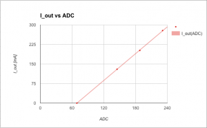
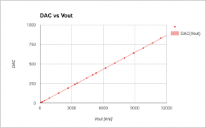
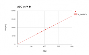
As I did not have the schematics at hand I had to reverse engineer the formula to calculate voltage/current based on ADC readings. I did some measurements and plotted in a Google Docs spreadsheet to find out
- V_in(ADC1_IN8) – given a reading on channel 8, what is the input voltage?
- V_out(ADC1_IN9) – given a reading on channel 9, what is the output voltage?
- V_out(DAC) – what is the output voltage given a DAC setting? (and the inverse)
- I_out(ADC1_IN7) – given a reading on channel 7, what is the current draw? (and the inverse)
To reduce complexity in the ADC IRQ handler, I pre calculate the ADC value that corresponds to the dialled current limit to quickly determine if we went over the limit. Here I ran into some issues as the ADC reading of the current draw differed between the two ‘5005s I had at hand. One of the units reported the wrong current draw which was tracked down to a different value when no current was drawn at all. The remedy is to take the first 1000 samples at system startup to calculate the ADC value for 0.00mA current draw and compensate in the calculations (see adc_i_offset & friends in hw.c)
Additionally, I currently collect a number of “over current samples” before triggering the OCP. This scheme needs some investigation.
Persistent Storage
User settings need to be persisted and this is taken care of by the past (parameter storage) module. This module uses two blocks for storing data. One is the “current block” and when it gets full a garbage collection is performed and the data is copied to the other block. Counters tell which block is the most recent one. In theory, power loss should not lead to corruption and/or data loss.
Graphics
An anti aliased rendering of Ubuntu Condensed is used in two different sizes for the UI. The font is found in gfx/fonts and consists of two files. The glyphs itself (eg. ubuntu_condensed_48.png) and one image describing the widths of each character (eg. ubuntu_condensed_48_width.png).

The widths are indicated by a white pixel in the first row:

The fonts are converted by ‘make fonts’ which invokes font-convert.py. The glyph PNG is converted to BGR565 (used by the TFT) and written to font-X.[h|c]. Each glyph is converted to a separate blob which speeds up blitting to the TFT. See tft_putch(…) in tft.c for usage. Blocking DMA is used to transfer the glyph data. One enhancement would be to have a list of DMA descriptors and fire the next DMA job in ISR context at the completion of the previous one. The icons displayed are handled in a similar manner (see eg. wifi.h) and are converted by ‘make graphics’. You should be able to change the font with little difficulty, in theory 🙂
Remote Control
The OpenDPS device can be controlled via the UART port and you can either connect an FTDI adapter or an ESP8266. The latter is the most fun. A simple serial protocol is used (see protocol.h and uframe.h). Either way you go, there is a Python script to talk to the OpenDPS device, dpsctl.py:
% dpsctl.py -h
usage: dpsctl.py [-h] [-d DEVICE] [-s] [-u VOLTAGE] [-i CURRENT] [-p POWER]
 [-P] [-L] [-l] [-S] [-j] [-v]

Instrument an OpenDPS device

optional arguments:
 -h, --help show this help message and exit
 -d DEVICE, --device DEVICE
 OpenDPS device to connect to. Can be a /dev/tty device
 or an IP number. If omitted, dpsctl.py will try the
 environment variable DPSIF
 -s, --scan Scan for OpenDPS wifi devices
 -u VOLTAGE, --voltage VOLTAGE
 Set voltage (millivolt)
 -i CURRENT, --current CURRENT
 Set maximum current (milliampere)
 -p POWER, --power POWER
 Power 'on' or 'off'
 -P, --ping Ping device
 -L, --lock Lock device keys
 -l, --unlock Unlock device keys
 -S, --status Read voltage/current settings and measurements
 -j, --json Output status as JSON
 -v, --verbose Verbose communications
The utility is agnostic as to how the OpenDPS device is connected. Provide an ip address and it will attempt to talk to that. Provide a TTY device and it will attempt to talk to that. For wifi connected DPS:es, you can provide the option –scan to find all OpenDPS devices on your network.
Any good old ESP8266 board with the UART exposed will work. Connect GND, RX and TX, build and flash esp8266-proxy (don’t forget to set your wifi credentials) and you should be good to go.
git clone https://github.com/kanflo/esp-open-rtos.git
cd esp-open-rtos
git submodule init
git submodule update
git checkout -b netif remotes/origin/sdk_system_get_netif
export EOR_ROOT=`pwd`
echo '#define WIFI_SSID "my ssid"' > include/private_ssid_config.h
echo '#define WIFI_PASS "my secret password"' >> include/private_ssid_config.h
cd /path/to/esp8266-proxy
make && make flash
Note that you currently cannot use the master branch on the main ESP Open RTOS repository as my PR for a function needed for multicast has not been merged yet.
The design of esp8266-proxy is quite minimalistic. It receives UDP packets on port 5005, sends the content on the serial port and returns the answer to the UDP source address and port.
When OpenDPS starts the wifi icon is flashing at 1Hz. When it goes steady your ESP8266 has connected to your wifi and told the OpenDPS that it is connected. Try scanning for it:
% dpsctl.py --scan
172.16.3.203
1 OpenDPS device found
Next try pinging it:
% dpsctl.py -d 172.16.3.203 --ping
The TFT should flash once as a visual indication. If you get ‘Error: timeout talking to device 172.16.3.203’, check if you swapped RX and TX. You can always connect an FTDI adapter on either RX pin on the ESP8266 and OpenDPS to debug the communication.
That concludes part two, please see part three for a description of how to upgrade your DPS5005 to an OpenDPS 5005.
Pingback: Open Source Firmware For A Cheap Programmable Power Supply | Hackaday
I have some questions:
1. Does the output quality (noise etc.) change with this firmware?
2. Could you add output power back to the display? It is useful to have it in some cases.
3. It seems Constant Current mode is not included. Was this also the case in the original firmware? It seems to be listed on some sites.
4. Do you have anything against me making a video about the project and update process (with proper sources of course)?
I love the project, I was actually pretty annoyed the DPS**** series lacks computer control capabilities around a week ago.
1. I would guess not. I have not had the time to look at the noise but plan on doing this once I build the DPS into a nice enclosure (where there would be room for caps, ferrite cores and a regulator for the ESP).
2. That is definitely doable, would have to reduce the size of the font though.
3. I think CC was in the original firmware. I chose not to include it as I am s software guy who only needs 3.3V or 5V with a limited current 🙂
4. That would be way cool, I’d love to see it!
The lack of CC is a bit of a problem for a hardware guy like me. I have never used more than 1A of it to be honest and my lab PSU already can do that…
We’ll see. Maybe I’ll just code it in myself xD
PRs are welcome!
Hi, I saw this great project on hackaday. Congrats! Constant Current mode and displaying the power output would be quite nice. By using constant current with a set maximum voltage this thing could be used as a quite nice battery charger or LED driver. CC mode is really helpfull.
Thanks! I omitted CC to save time. Chances are slim I will do the CC implementation though as I neither charge batteries nor drive a great many LEDs 😀
Any ideas how big work it will be implement mWh “trip meter”? Developing iot things many times you want know how much power this take with one wake up period. Sampling it with quite fast rate would give really useful information how fast your device will drain battery.
Actually, the single most important measurement is your sleep current as your IoT node will sleep for most of its life. Then we are talking micro amps and the resolution of the DPS probably is not sufficient for this. The EEVblog uCurrent is perfect for this though.
This is fantastic work.
Can we use it in some way so that the functionality remains with the added benefit of being able to remote control it?
Thanks
Thanks! Unfortunately no as the stock FW does not have a serial interface, and I will probably not implement the CC mode.
Hi Johan,
What do you mean no serial interface? here is what you wrote:
“The goal of OpenDPS is to reflash the stock DPS5005 (and friends) with a firmware that has the same functionality, has a less cluttered user interface and is remote controllable via wifi or a serial port.”
Thanks
I meant that the stock firmware does not have a serial interface for remote control. OpenDPS has.
Sorry for my ignorance. 🙁
So if both the hardware and OpenDBS has serial interfaces what is the reason that it can not be remotely controlled?
Thanks
And I can see a transmission icon on your design screen. So did you add some hw to make it communicate?
Thanks
Yes, a development board with an ESP8266.
No worries. OpenDPS _can_ be remote controllable. the stock FW cannot.
Hello!
Really good worl!
I just got 1 question: You know, how the TFT is connected? (I²C, 2/3WireSPI?)
8 Pins – 2 supply -1 NC – 1 LED still 4 to go….
TNX
The TFT is connected using 2 wire SPI (CLK, MOSI) with the addition of a reset signal and the address/data pin.
Is it possible that the adjustable current limit of the original product uses another DAC to set the limit? Ideally you don’t want to depend on the processor for current limit, as that would allow the load to go overcurrent for several or many microseconds before the firmware responds, while in a normal power supply with current limiting, it is done by direct feedback to the regulation circuitry, and operates much faster, limited mainly by the loop bandwidth of the regulator.
Were I designing such a product, I’d use another DAC to control the current limit, but in a product so inexpensive, I suppose all bets are off.
Awesome work! I am really excited to receive my DPS5005 so I can try out your firmware. The interface does look much cleaner and sleek. Kudos on your hard work, it will be very useful to people building adjustable power supply. Thanks for sharing!
Thanks!
Great project; thank you.
Unfortunately, it is, for some of us not usable without the CC.
Thanks! There is cc support on the cc branch of the GitHub repo. This branch and master have diverged somewhat and I should pull them together when time permits.
Just discover this firmware you make, great job!
I’ve a few suggestions for evolution:
1 – Add CC (seems already on going)
2 – Add a simple graphical scope of mA vs time or W vs time, for the last minutes and give statistics about it since last user reset. This is great for profiling power consumption on low power circuits that keep sleeping for the most time.
3 – Add a tools menu where the user could select a battery charger option: ex select PB/NiMH/Li-Ion, num of cells in series to charge, cell capacity in mAh, max time until power off, all user configurable. And also detect full charge by monitoring the charge current profile for the selected chemistry.
4 – Is the hardware able to emulate via firmware a load charge ? If so that is my other suggestion.
Thanks! #2 is a cool idea. I’ll leave #3 to someone charging batteries and raising pull requests 😉 Not sure what you mean with #4 though.
So, for 2 on top of mA and W also mAh.
For 3 a simplified way is to just add a configurable timer shutoff and mAh shutoff options.
For 4 i mean a mode to simulate a programable dummy load, loje this project http://store.iteadstudio.com/index.php?main_page=product_info&cPath=29_31&products_id=301
Johan,
I’m tying to communicate with my DPS5020 which has a USB connection with my ODROID C2 – Ubuntu 16.04
– python3 but have some problems with the instruction ~$ pip install protocol and uframe
Can you help me out ? I get the error : Could not find a version that satisfies the requirement
Hi Luc. “Protocol.py” and “uframe.py” are included in the git repo. Did I write “pip install …” in the instructions?
Johan,
I’ll give it a try with git repo. Thanks anyway, in the meanwhile I found the MinimalModbus 0.7 package. Works fine to.
Today, RD announced a new USB tester gadget that appears to have the same display as the DPSes and I would be really surprised if it is not also based on the same or a very similar STM32:
https://www.aliexpress.com/store/product/x/923042_32845522857.html
I think I’ll order one to see what’s inside.
Just for completeness: Meanwhile I received one of them, and it does not contain an STM32 as I expected, but an STM8S005K6T6C.
Is there anyway to re-flash the original firmware ? Would the manufacturer provide the firmware ?
Just wondering.
AFAIK the original FW is nowhere to be found. Since read out protection is enabled on the STM32, RD Tech seems like they don’t want the FW floating around.
For anybody interested in a more complete product with enclosure and 230V AC to 50V DC power supply included I bought one of these from AliExpress: https://www.aliexpress.com/item/32805072825/32805072825.html
I have done a quick tear down and the enclosure seems like good quality and the AC to DC powersupply seems acceptable. I’m still waiting for my ESP8266 board to arrive (with support for external antenna as the enclosure is metal) and a ST-link2. One nice thing about the metal enclosure is that there is a micro USB port hole without any female micro usb connector pcb – this could be repurposed as a reprogramming port.
hello, I have a contribution, the U7 is a 24C02 memory