Update Aug 28th: The BOM for all variants is now on Github. Please see the notes at the end if you want to build a Commadorable 64 yourself.
The ILI9341 based QVGA displays found on eBay for €4 are well suited for making small screenlets telling the current temperature, weather forecasts, traffic situation to work and spreading them over the house. As PCB design is both fun, cheap and rewarding I did a custom PCB for these tiny displays. Actually, I made three, one for each of the 2.2″, 2.4″ and 2.8″ screens. The 2.8″ version has not been produced but the smaller variant have and work well. From 2.4″ and onwards there is (untested) touch support on the screen modules.
The “Hello World” application for this project also named the PCBs. I call them Commadorable 64. Here is why:
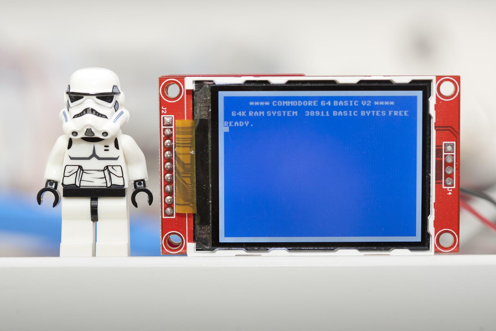
The cursor blinks but I resisted the urge to create an animated GIF. “Commadorable 64” is a play with “Commodore 64” and “adorable”. It has been scientifically proven that those for whom the Commodore 64 played a significant part of their childhood will look at the 2.2″ version of the C64 start screen and react the same way as cat people looking at kittens. Heads will be tilted slightly sideways, smiles appear and sounds like “naaaaaaaw” will be heard. I have one of these at work and depending on childhood experiences people will either go “what?” or “naaaaaaw”.
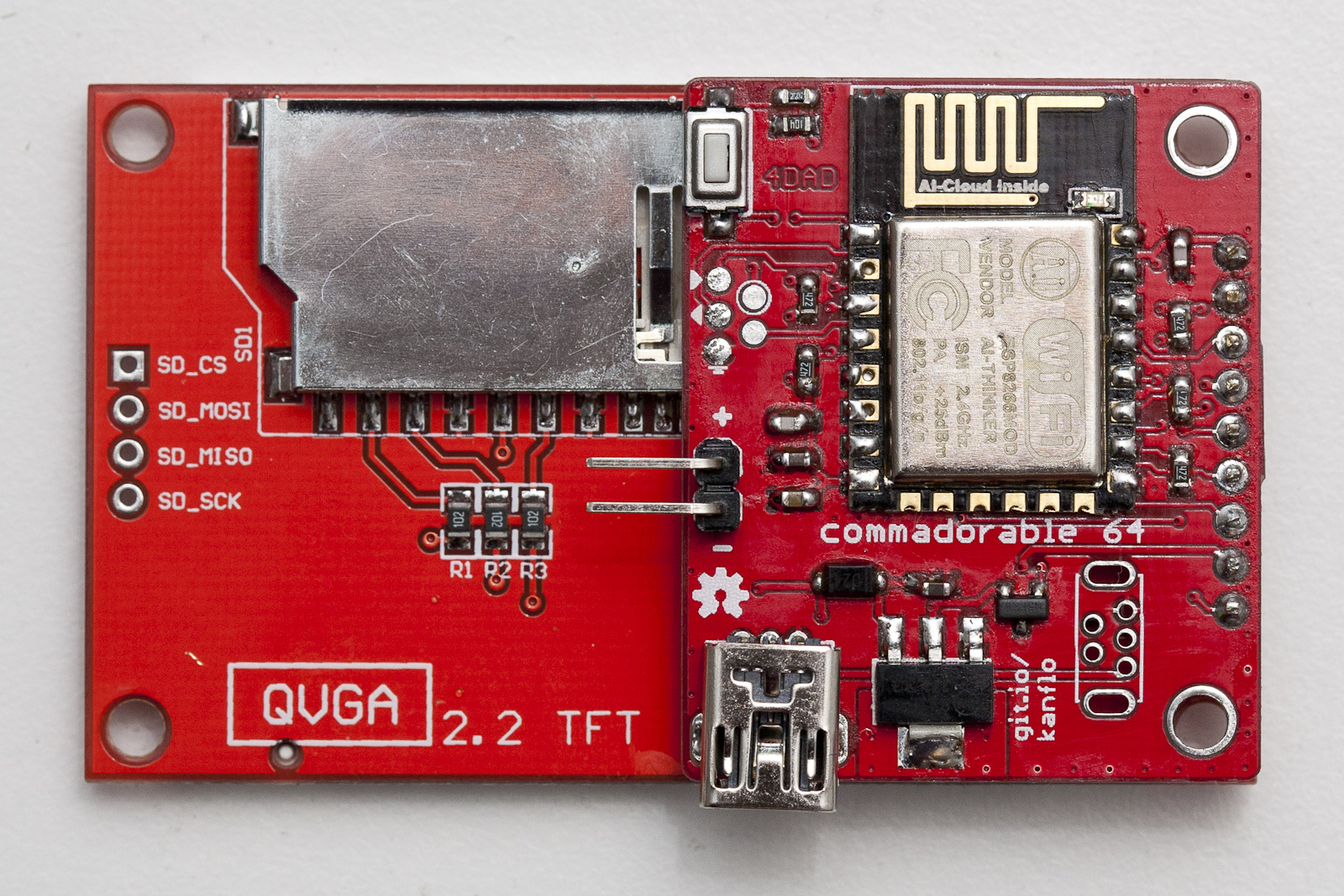
The PCB is soldered directly to the pins of the ILI9341 module. Some of these screens will probably end up in other applications in the future. The other day I read about openframe.io and adding support for these would be fun.
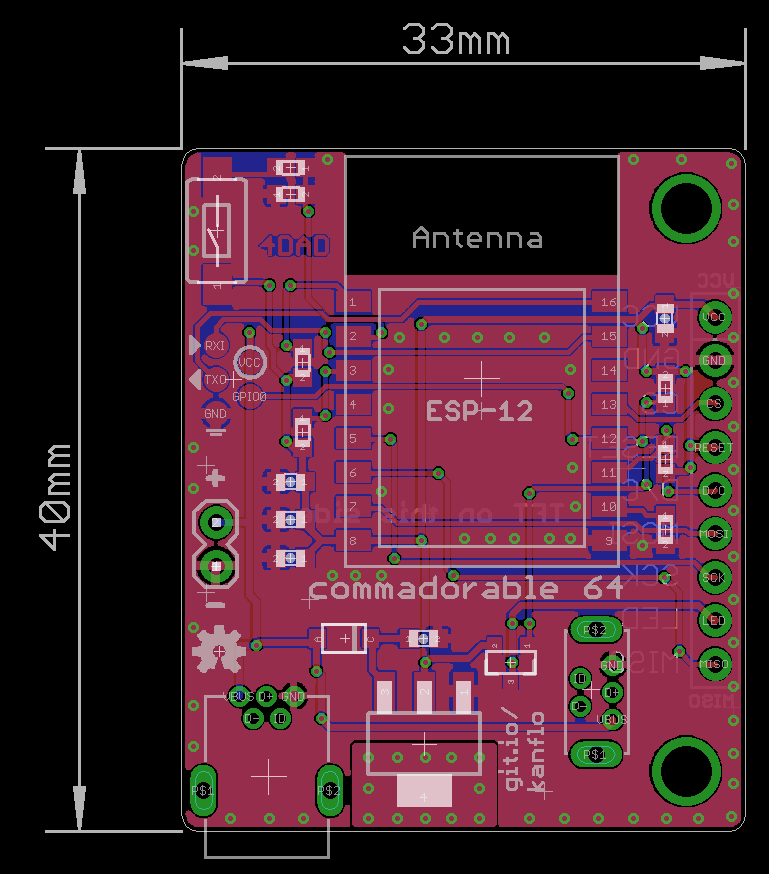
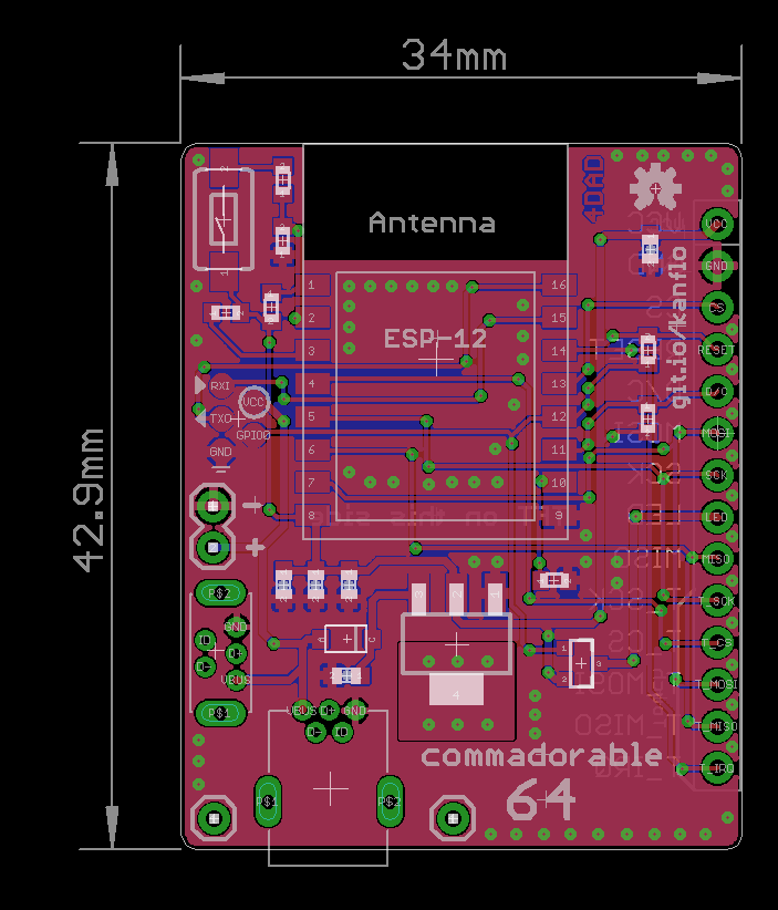
The PCBs can be ordered from DirtyPCBs.com, 2.2″ with a bonus AAduino and 2.4″ version with touch. The BOM consists of the usual components for my ESP8266 designs. We have 0603 resistors and capacitors, a 3x6x2.5mm momentary push button [eBay] for displaying the IP address, a SOT23-3 P-mosfet to control the backlight, an LM1117 voltage regulator and a SOD-123FL schottky diode for reverse power protection and optional mini USB connectors. The PCB can be powered in three different ways depending on personal preference (well, four including the esprog interface). There are footprints for normal [eBay] and vertical [eBay] mini USB connectors, depending on if the module is to stand on a table or hang from a wall (Eagle parts available on Github). In addition there is a 0.1″ header for power. All power paths are protected by the diode.
Further update Aug 28th. I see some 20+ orders on DirtyPCBs for both Commadorable 64 variants which is great fun and I would really love to hear what you will build. I have some recommendations you might find useful. I have received a few broken ESP-12e/f modules on eBay over time and one broken ILI9341 module. Because of that I always try the modules before soldering them using my Esparducam board with the ESP Pinlet add on board. When a module passes testing I flash it with the ESP Open RTOS OTA basic demo meaning I can OTA any device directly after soldering. Also, you will note there is no FTDI connector on these boards, the reason is described here. As UART output is still useful, I have one “development” variant with leads from an FTDI connector soldered to the GND/RXI/TXO esprog pads. Oh, and I also have one Commadorable 64 board with a female header for testing the ILI9341 modules before soldering them. If you have any questions about building the boards, sound off in the comments below.
Code and schematics on Github, as always.
Pingback: The AAduino – Johan Kanflo
Pingback: Nerd-Bait: ESP8266 + ILI9341 Screen | Hackaday
Congrats on making Hackaday!
For those of us with only through-hole skills… will there be a PTH-only version, or perhaps a way to order preassembled boards…?
Thanks! There will not be a PTH version (sorry) but ordering is possible in theory. I am currently working the theory out for my AAduino project. I would however highly recommend learning SMT mounting using a hot plate, its really fun and rewarding!
Yes, you have to just buy hot air gun (35$) and then it is easy 🙂
Could it run a Commodore 64 emulator? Load programs via WiFi used as a virtual RS232?
I know a PC can serve as a virtual disk drive via RS232 to a 1980’s home computer because someone has done it with a modification to a TI-99/4A RS232/PIO card and a program for Windows. The modification converts one of the two serial ports to work with a modification to the card’s DSR, Device Service Routine, essentially a device driver built into the device.
TI made a very flexible system with DSRs. The computer knows nothing about any hardware other than what’s in the computer console itself. It has a series of locations on the expansion bus it scans for DSR’s at startup. A DSR adds seamlessly onto the operating system on the GROM chips in the console by providing new device names and commands. For example the floppy controller adds the DSK1 DSK2 and DSK3 devices and commands for them. 3rd party controllers typically had DSK4 and more commands.
TI not only had perfectly functioning “plug and play” in 1977, they made it future proof with the flexibility to add *anything* anyone could dream up to connect to the computer.
It could as someone has already ported a C64 emulator to the ESP8266. I would not expect it to be cycle/raster exact so games might not work but I could be wrong. Impressive future proofing by TI there. On a side note, the C64 managed to future proof it self in a rather special way. I know guys in their 40s who still do C64 demos 😀
IBM did a similar system with their MCA bus, as far as integrating the hardware. But instead of making the configuration 100% hardware/firmware they made it so every device had to have a special setup floppy to program the BIOS for it. Then the operating system had to have it’s own driver to be able to use the new device.
With the cheapness of memory chips now it should be feasible to ship peripherals with the OS driver on the device so one could simply plug it in, turn on the computer and the OS finds the driver and installs it. No more lost drivers! Downloadable driver updates could update the storage on the hardware so no more hunting for and re-downloading the latest drivers when doing a clean install.
Too logical, won’t happen any time soon. Or the industry knows TI did it nearly 40 years ago (except the updateable part, but some 3rd party hardware has in-situ writeable DSR) and thinks it’s “old school”.
Pingback: Cool ESP8266 Display Project – Linux & Liberal Arts
Are you planning to sell fully assembled versions of this device ?
No immediate plans but I am toying with the idea of building and selling the rest of the PBCs I get from DirtyPBC. I seldom need all of the 10 boards I get 🙂
Well, please put me down for one!! Would you consider assembling it as well for a fee?
Have you tried any Arduino base LCD library on your setup? Perhaps the Adafruit ones?
Iv found the Arudino environment is great for use with the ESP8266, fantastic libraries to use, you spend more time being creative with hardware and less time trying to get stuff “working”.
I have considered assembling too.
I have not tried any Arduino based libraries but that should work pretty much out of the box as I use a port of the Adafruit library. Well, I must have been a bit tired when I wrote that. The first version actually used the ESP8266 Arduino environment, I have pushed the sketch to Github.Count me in too! My 2 Qs;
1. Can you describe the BOM in detail, e.g. regulator 5V or 3.3V, which P-mosfet? etc.
2. Any GPIO pins left?
Thanks and CONGRATS. Looks absolutely amazing!
Thanks! I will get back to you wight the BOM but the regulator outputs 3.3V (. For the non touch version GPIOs 5, 15 & 16 are free. For the touch version only GPIO 15 remains.
I would also like the BOM, I already even ordered the boards, as i was anxious to find out how the dirtypcb process works. Thanks for the great work 🙂
I may have some boards spare in EU!
Thanks! The BOM is now available on GitHub and I added some help in the article.
Wish the board had a silkscreen for component labels. Any possibility of labeling them on an image? I’m sure its possible to figure out but my board is not working. I think I may have a component in the wrong spot! Thank you for publishing this project!
Sometimes wishes come true 🙂 I added silk screens for the 2.2″ and 2.4″ versions. Additionally, I created the “build sheets” I use nowadays when mounting.
Pingback: Cheap wireless ESP8266-based display – TechniGEM
Pingback: Nice little TFT screen adapter board | esp8266hints
Johan,
Great work, is the pcb artwork available? would be great I have needs for a similar board .
regards
Dans
Thanks found the files, awesome job
Thanks!
Pingback: The AAduino – Johan Kanflo
I ordered some of these boards awhile back but just recently assembled one. When I power the device I can see the “cursor” blinking but c64.bmp file doesn’t seem to load though. I can see the serial messages and they indicate that the file was found and loaded but I don’t see it on the screen. Any ideas as to what my problem might be?
Found the issue, the lastest version of the Adafruit_ILI9341 library requires some changes to the bmpDraw() function. Once I updated this, I now see the c64.bmp loaded on the screen.
Thanks! Would you mind raising a pull request or just send me the output of ‘git diff’?