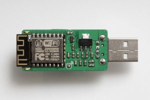
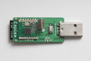
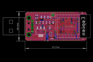
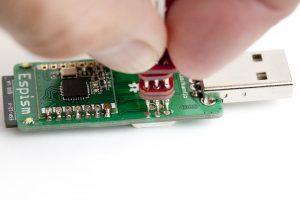
The ESP8266 has taken the maker community by storm and the hype is well deserved. Before the ESP we had the HopeRF ISM radio RFM12 and its successor RFM69. So is the ESP8266 an RFM69 killer? I would say no. Hell no even 🙂 The RFM69 is still very well suited for certain applications and the ESP8266 will not run for 2+ years on a set of AA batteries. The two can however play nicely together as a low cost ISM/wifi bridge. I did a custom PCB for this in the shape of a somewhat large USB stick, dubbed “Espism”.
Currently it works as an ISM sniffer posting the received packets on the MQTT topic espism-<macaddr>. Packets are posted in hex followed by the RSSI value:
espism-5ccf7f147cd Hello from 172.16.3.120
espism-5ccf7f147cd 016340630001000000c375b642[-27]
espism-5ccf7f147cd 630180[-57]
A set of four LEDs indicate received packets. Well three LEDs as I made a mistake on the ground plane. The MQTT server IP and RFM69 network information is hard coded into the binary.
I ported Andreas Heßling’s STM32 RFM driver to the lovely ESP Open RTOS, my swiss army knife for ESP8266 development. The type-A right angle 90 degreee USB connector and 3x6x2.5mm push button can be found for little money on eBay. The push button currently serves no purpose but the plan is to perform a “master reset” of the device using this button. The rest of the BOM consists of 0603 resistors and capacitors, an LM1117 3.3V regulator and a SOT23 P-mosfet for driving the 0603 LEDs. Oh, and the ESP12F talking to an RFM69CW. The BOM should add up to about the price of lunch.
Code and schematics on Github as always.
