Somehow, the cord to the external temperature probe got ripped the out of the temperature display in the bedroom. My wife insisted on us purchasing a new thermometer but as an engineer I immedietaly saw the opportunity to build hardware and write software. Spending lots of time and resources on “engineering joy” is not something one can do at work but in one’s sparetime the sky is (almost) the limit.
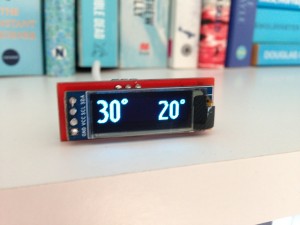
So instead of spending about a dozen Euros on a new thermometer I designed and built a PCB and wrote code which was a lot more fun and educational. And way more expensive 🙂 The result is the Wife OLED that displays the current outside temperature as well as the forecasted temperature in 8 hours. While the morning might be cold, it is nice to know what the temperature will be at lunchtime.

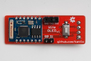
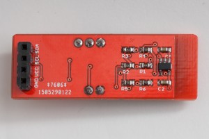
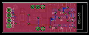
As the OLED display would be always on and close to a power outlet I choose a wifi solution and went for the the ESP8266, more specifically the ESP-03 module for its small size. The OLED was found on eBay, is a mere 0.91″ large and has an active area of 128×32 pixels. The device runs from a USB charger and an SPX3819 LDO provides the 3.3V the ESP and OLED needs. I designed a PCB in Eagle and had DirtyPBCs.com produce it. As the PCB is quite constrained on size there is no full FTDI-style connector. The RX/TX pins and ground are the only ones available for programming and a small tactile switch is used to get the ESP8266 into download mode.l
Looking at the software side, it turned out most of the work had been done by Nathan Chantrell (and others). He used a 128×64 pixel OLED display and the driver seemed to originate from the Arduino OLED driver by Adafruit. As I had chosen a 128×32 pixel display the driver needed some work. Also the available fonts where too small to be readable from across the room so I rendered Ubuntu Condensed in 28px and 32px. The larger font will be used for displaying the current temperature and the smaller one for the forecasted temperature. The device subscribes to the MQTT topics `home/temperature/outside` and `home/temperature/forecast` and displays whatever arrives on those topics.
The current outside temperature comes from my setup with a Tiny328 node equipped with a DS18B20 probe and a Raspberry Pi gateway (a future post). The forecasted temperature is pulled from the open data feed of the Swedish Meteorological and Hydrological Institute (SMHI) using the script get-weather-smhi.py.
The HW schematics (and gerbers!) as well as the SW is found on GitHub.
A note one year later: The OLED display will start to deteriorate after about half a year. It will still be readable but the pixels get “worn out” and will not be as bright. I would not recommend soldering the display to the PCB for this reason. Nowadays these displays retail at €2.50 on eBay so a replacement now and then is acceptable.


Great little project! I was wondering if you could point me in the direction of where you got the short female headers you used in this project. I’ve had a hard time locating a supply of them.
Cheers,
Thanks! I found this one in the lab at work and have failed to source it too I’m afraid.
Since your project is a while ago I like to ask you about the lifetime of that display. The datasheet writes somethoíng about only 5000 hours. Does it still work properly?
It is true the display has a limited life time. I see deterioration after about six months so the display needs replacing once or twice a year. This obviously is not optimal but I have accepted this shortcoming as the display works very well both in daytime and nighttime. A TFT would probably emit too much light and ePaper is of course not visible when it’s dark. Thanks for reminding me of adding a note not to solder the display to the PCB.
So that confirms the info from the datasheet. I noticed that the display brightness/contrast is still fine for most situations with a quarter of the maximum brightness. Then it will hopefully live much longer than one year.