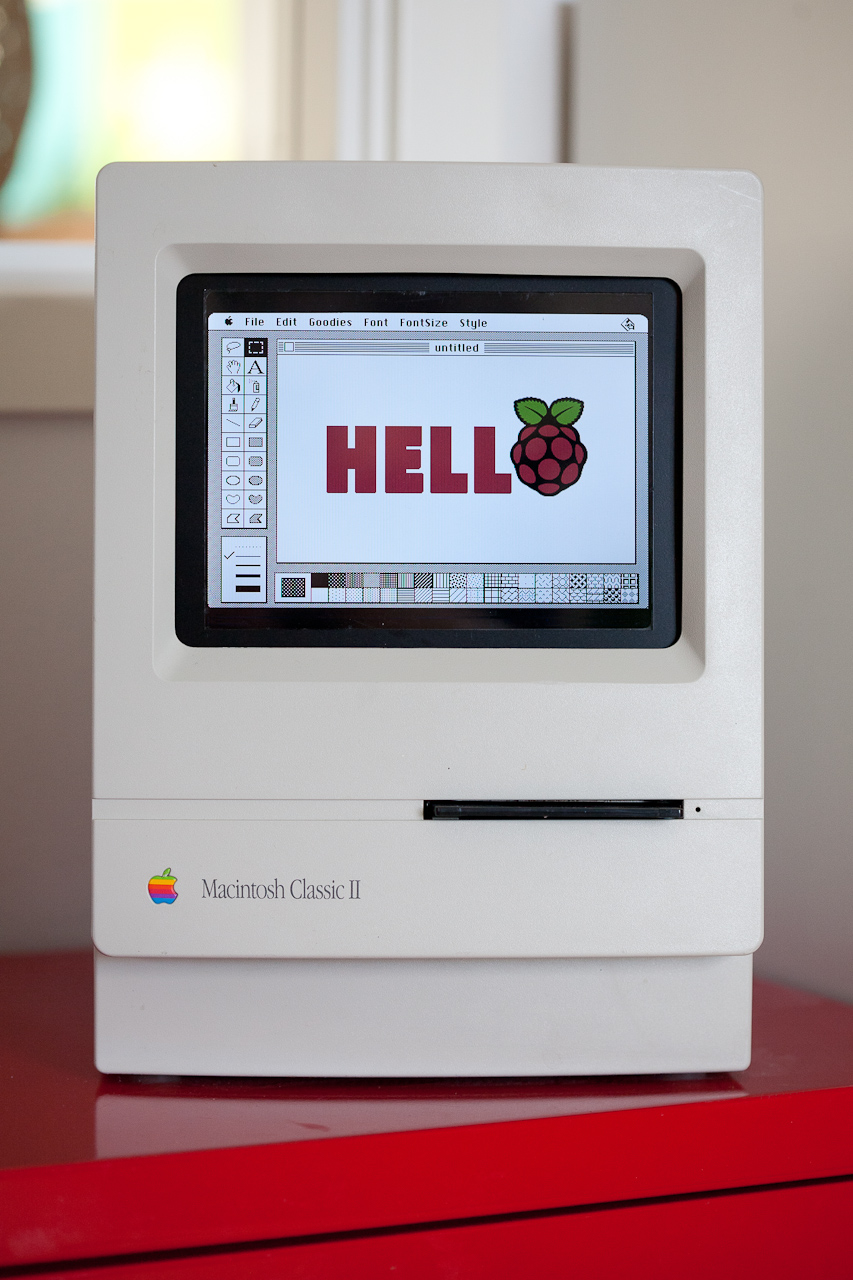
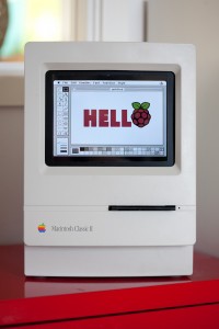
The Macintosh Classic is somewhat special to me as it was my first computer I used for other things than just games. Not suprisingly perhaps as the line games was somewhat limited although there where classics like Dark Castle, Apache Strike, Empire and Deja Vu. That aside, I have had a Mac Classic II in my study for years reminding me of where my career in IT started and it was time to pour some life into the old machine (click for hires images or see the gallery at the end).
The obvious choice was to use a Raspberry Pi. Placing Pis in old macs is by no mean a new idea but I wanted to make something different and above all make something as sturdy as the old mac. The newly born Mac should be able to ride the bus as my old Classic did at times meaning I could not just put loose hardware into the box. Things needed to be fastened. I set out with the following specification:
- Raspberry Pi
- TFT screen
- Speaker
- Internal USB hub
- External connectors for USB and ethernet
- Working programmer’s key and reset button
- Working floppy drive ejector motor
- External 12V power supply
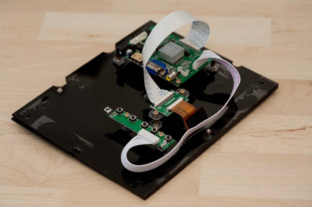
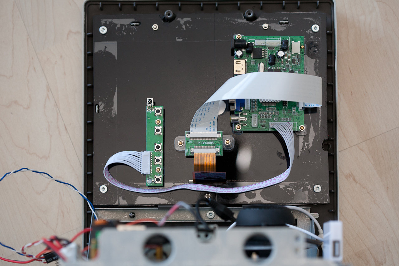
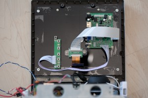
I had found this 8 inch TFT screen on eBay (update June 5th 2017, I have found a much cheaper variant on AliExpress that by the looks of it is identical) but as you can see the frame has no mounting support. Adding the cabling and driver board with its adapter boards sums up to quite a mess. How do we mount this nicely inside the Classic? Plexiglass to the rescue! I cut out two sheets of plexiglass and placed the TFT screen between them. Glued piexes of plexiglass on the back sheet keeps the TFT screen from falling out. The different boards are placed on spacers mounted on the back side plexiglass sheet. The front and back sheets are held together usings screws.
The final part was mounting the “screen module” inside the Classic. As I had thrown the old CRT screen out, it was only a matter of drilling the right holes in the plexiglass screen module and mount it the same manner the original screen was.
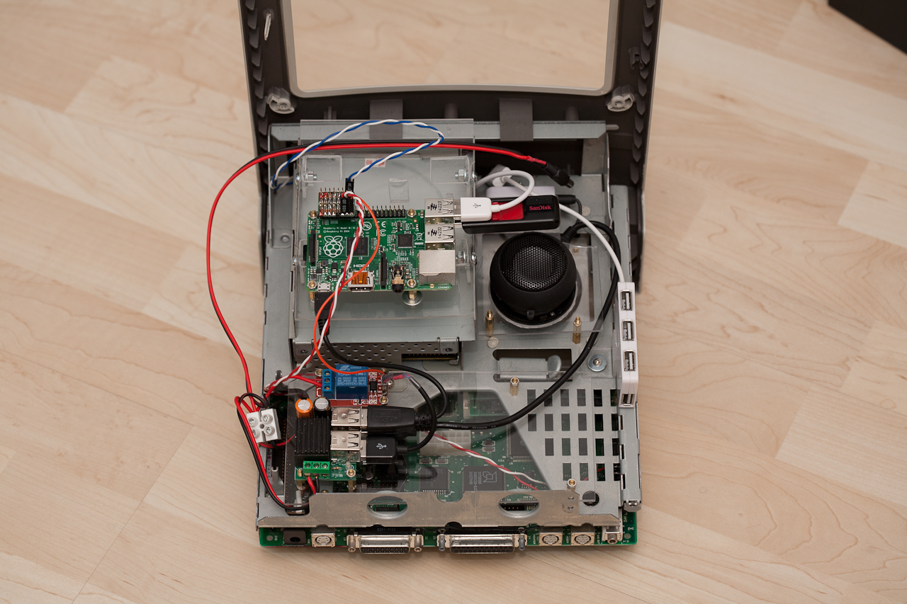
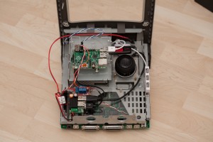
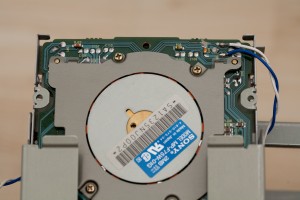
Next was the mounting of the Raspberry Pi. For this I reused the hard drive bay where I mounted a piece of plexiglass holding the Pi on spacers.
I wanted to bring back the yawning like sound of a Macintosh ejecting a floppy disk. The idea was to have the Mac automatically eject an inserted floppy with a delay. So how did the old Macs detect the precense of a floppy disk?
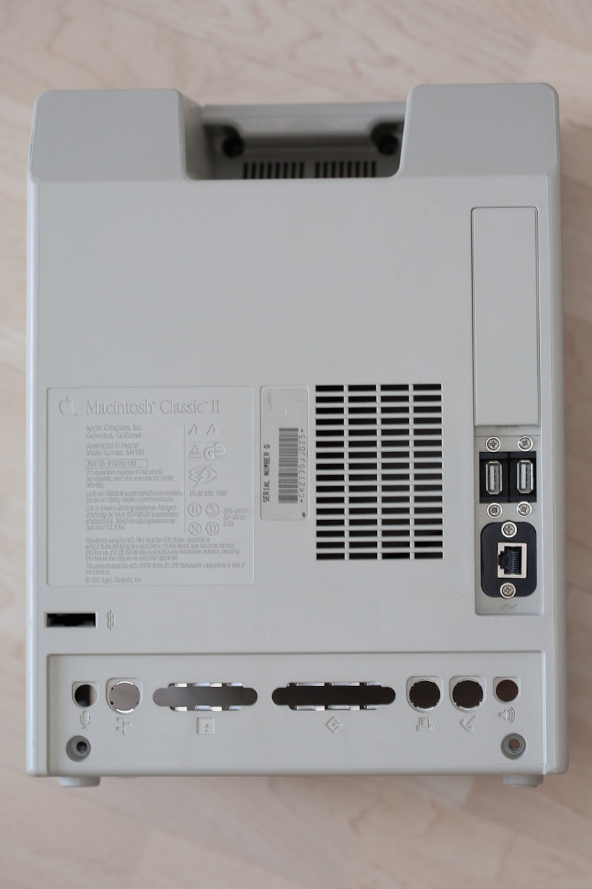
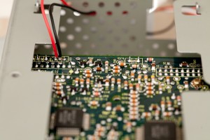
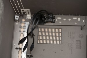
There are a number of micro switches sitting in the front of the floppy drive. These will be pressed (or not) when a floppy is inserted into the drive. From right to left they will tell us
- Is there a floppy present?
- Is is write protected?
- Is is a single sided or double sided floppy?

<side note>Floppy disks back in the days had a write protect switch on them consisting of a small piece of plastic that would open or close a hole. An open hole indicated that the floppy disk could be written to. Another hole in the floppy disk indicated if data would be written on one or both sides of the disc. Switches 2 and 3 above would be not pressed if the corresponding hole was present on the floppy disk.</side note>
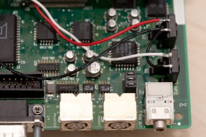
For this project, I only cared about switch #1. Deciding the floppy drive would never see real action again, I disconnected the switch from the rest of the floppy drive PCB by severing the traces. Soldering wires to the switch and attaching them to the Raspbery Pi GPIO header, the Pi could now sense the precense of a floppy disk. Next was the ejector motor. It runs on 12V (as the TFT screen) and I purchased a relay on eBay that the Raspberry Pi could control.
On the left hand side of the old compact Macs was the programmer’s key and the reset button. The former would enter the debugger built into the computer. I wanted to connect these to the Raspberry Pi so once again I severed some traces. On the the motherboard this time.
For power, I purchased a 12V to 5V converter with quad USB output on eBay. This together with the relay was mounted on a sheet of plexiglass that was mounted on spacers in the back of the computer. The speaker was mounted in a large hole i drilled in (you guessed it) a piece of plexiglass mounted on (guessed it again?) spacers. As the sound quality on the original Raspberry Pi was quite poor I added a USB sound card (also from eBay). I desoldered the microphone connector on the Mac’s mother board and replaced it with a power jack that I connected to the 12V/5V converter. An old Western Digital USB disk power supply provies the 12V needed.
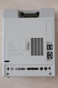
Last but not least, I added two external USB ports and an ethernet port. Both use passthrough cables found on eBay (search for “USB 2.0 A panel mount extension cable 25cm” and “ethernet panel mount extension cable 25cm“. They are mounted on the last piece of plexiglass that is glued to the inside of the case. I reused the holes where the original 220V power cable connector and power switch where located.
A simple python script checks the programmer’s key, the reset button and the floppy detection switch and controls the eject motor. Pressing one of the keys will play the lovely old Macintosh Quadra chime. A long press will shut the Raspberry Pi down.
Floppy ejection was a bit tricky. The eject motor is a simple motor and not a servo meaning you cannot tell it to goto a position and back like those servos you have been playing around with using your Arduino. The motor needs to return to (roughly) its original position or it will be impossible to insert a floppy again. I have no idea how this was accomplished back in the days but this simple algorithm (based in parts of my recollection of the old floppy sound) did the trick
- Start motor
- Wait for lost floppy presence
- Wait for 1 second
- Stop motor
I am quite pleased with how this mod turned out. There is nothing loose inside the case that can fall over, get tangled up and cause shorts. By accident, the Mac was drop tested from a height of one meter. It survived, nothing came loose.
I have some future plans for HW modifications including a touch screen, replacing the clicking mechanical relay with a transistor and I should add a fuse to the 12V line for safety.
Most of all, I need to add software to make the old Classic actually do something. But that is for a later post.
Update 26th of June 2016, the python script running the show is now on Github.
Update 5th of June 2017, added AliExpress link to cheaper display and eBay links to USB/ethernet passthrough cables.
Gallery

Pingback: ADS-B skygrazing | Johan Kanflo
I am curious to know the code used to restore functionality of the disk drive, the programmer and reset buttons, and the quadra chime. What are the scripts used?
I am currently travelling but I’ll dig out the Python code used when I get back home.
It’s now on Github.
Could you be paid to source+produce a fully working setup and ship it? I have no hardware skills but love what you have done!
That could work in theory but would be rather expensive as building this setup is quite time consuming.
the power supply you bought, 12v to 5v, was it like this?
http://www.banggood.com/12V-To-5V-DC-DC-Converter-Module-With-USB-Output-Power-Adapter-15W-p-937209.html
I use exactly that one. Originally I used another one (the one in the original images) but it failed after a year. I took the one you found and attached it to a prototyping PCB where I added screw terminals for 5V and 12V output.
Any idea, your talking about side programmer buttons, I have a Macintosh SE/30 with a broken PCB (battery leakage gone real bad!)
But there no buttons on the right or left side of the case, where are you putting the on/off buttons?
It seems the “external part” of the programmer’s key and the reset button have gone missing on your SE/30. IIRC, this part was included with the computer but one could choose not to attach it. If you open the case, you will find two micro switches on the PCB, see the picture above. If nothing else, you could press these buttons using paper clip through the side vents of course.
Is this what you used for the USB ports as passthrough cable 2 of these?
http://www.ebay.co.uk/itm/1m-3-3ft-USB-2-0-A-MALE-to-A-FEMALE-Extension-Cable-Cord-Extender-For-PC-Laptop-/381881800571?hash=item58e9edd77b:g:F~oAAOSw5cNYTlz7
That’s right, I used a 25 cm version. I have added links in the description.
Hello,
I want to make the same project as you.
My first idea is to power up the raspberry and the screen with 2 different adaptors, because I’m not an electricist…
I bought the same lcd screen at Aliexpress, but I don´t know how to power up it. Do you use a 5V power adaptor? With how many Amps.? I’ve tried with a mobile power adaptor with 5V/3Amps and nothing appends…
Thanks for your time, and sorry for my poor english…
Cool, please send pictures when you are done. The screen needs 12V, that is why it doesn’t turn on. I feed the Mac with 12V and use a 12V->5V converter. The external 12V is fed directly the the screen and the 5V goes to the RPi.
I have a crazy question and I know that this might not be an easy question but as they once said, enquiring minds want to know.
Is there any way to get a raspberry pi to connect up to the original CRT?
Is there an ounce of a chance?
Legendary hacker Sprite_tm has done something similar with the original CRT. Others seem to use a replacement 9″ CRT (probably with composite or VGA input).
This is great and I am currently working on a similar project with an SE/30.
I don’t quite see how you fitted the screen, or rather how you dealt with the curve to get a tight fit.
I have pondered with making a 3D printed surround to hold the LCD screen on the outside of the case that will hide the curvature and produce a tight fit but the colours will look odd.
Any photos or advice would be great.
Many thanks
Neil
I tried to deal with the curvature by bending a sheet of plexiglass. It turned out quite alright but added reflections of course so I got rid of it. Right now it looks slightly weird from when viewed from the side but I prefer that over reflections 🙂
I’ve read somewhere about a guy who just went to a glazier and got a 4mm piece of glass cut to cover up their LCD screen.
I’m beginning on a similar project with a Mac Classic II. I really love the original power rocker switch in the back of the case. Any thoughts on possibly wiring that switch to power on my Raspberry Pi 3+ ??? Thank you.
I have a question about your “external 12v power” what do you use to power it? Is it like a battery?
I use a DC adapter from an old Western Digital external hard drive.
+1 on needing to figure out how to make the screen curvature look sane. I’ve tried printing a bunch of curves and can’t get anything to look right. Argh.
If anyone manages to design it (cad, openscad, etc), please post here!
Cut the original crt and use it. That’s what I am doing…
http://retroguy.blog/2019/12/23/new-project-in-the-oven-classic-mac-as-a-modern-game-media-station-with-the-original-crt-glass/
Now that is cool! Looking forward to see the final build.
Silly. If you had used the original CRT monitor then this would be somewhat interesting. Instead you merely connected together some off the shelf bits into a plastic hull. It could have been a toaster. Not at all interesting or clever.
I am a TTL kind of guy so anything high voltage scares the bejesus out of me 😃
That’s a bit harsh, besides, the Mac Classic CRT is a tricky beast because it runs on a non-standard VSYNC and HSYNC refresh rate. I have been attempting to build out a Mac Classic logicboard -> external PSU and monitor out and, although the video out is a simple 1Bit Black/White with SYNC, the rates are so strange that I’ve not yet found a multiscan LCD screen that can handle the video SYNC from the logicboard. I’m thinking that eventually I’ll have to go down the FPGA path and be done with it, :p.
Personally, I don’t blame you for not re-using the CRT