Updated on September 2nd 2017.
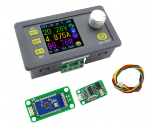
It’s exciting to see the continued development of the DPS5005 and ‘3005. Today Rd Tech released a version with USB/Bluetooth connectivity and I just ordered one to make sure OpenDPS runs on it. The new version seems be fitted with a JST has a JST GH connector which makes connecting an ESP8266 or a serial port a bit easier. It also has different MOSFETs by the looks of it.
Now I only need to wait 25-36 days for shipping. The wait is over and with a minor tweak (DAC needs to be disabled when turning off the output) OpenDPS is fully functional on the new DPS5005 “communication version”.
UART changes
There is no need to solder the UART anymore and you get a cable with the device. You can cut the cable in half to connect to your ESP8266 or FTDI-adapter but I recommend buying a set of cables and connectors from eBay. Search for “10SET JST GH Connector plug with Wires Cables” and get the JST-GH 4 pin kit. The pinout of the cable depends on what end you insert into your DPS (as both ends have female connectors). Thus, I will not say “red is VCC” as it will be “red is GND” if you connect the other end and observe the holy smoke. Look at the pinout below and determine which wire is which. The silkscreen is “V R T B” which I think should have been “V R T G“.
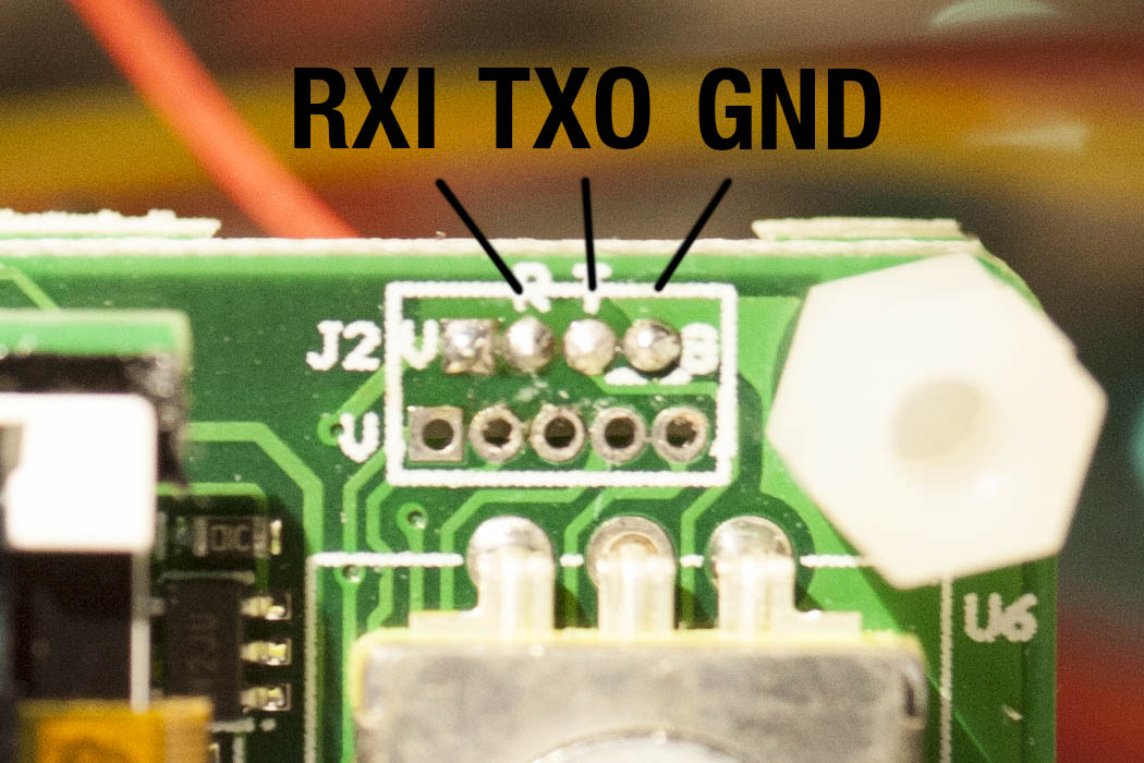
RXI indicates that this is the RX input (sic!) of the DPS5005. and TXO is the TX output (re-sic!) of the DPS5005. People have mixed up RX and TX for ages, calling your signals RXI and TXO will put an end to it. To the left of RXI is VCC which in the previous version could not power an ESP8266. I have not checked if the regulator has been changed to something more powerful in this version.
JTAG changes
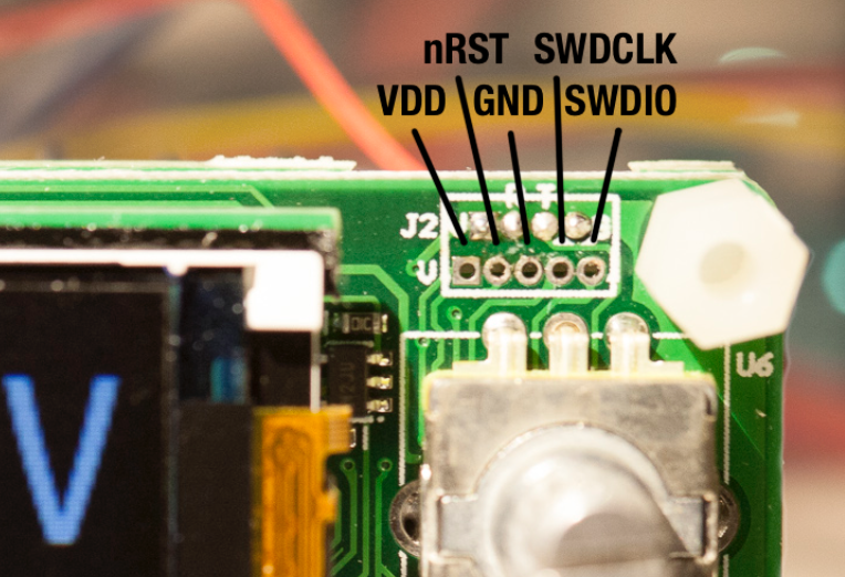
The JTAG connector on these new devices is called JST-GH and has a tiny 1.5mm 1.2mm, 1.25mm spacing and there is not room for running the JTAG wires toward the back of the device which makes a permanent JTAG solution cumbersome. When flashing, I simply pressed three test needle probes agains the GND, SWCLK and SWDIO connectors. Then again, most people will not need permanent JTAG but we all want a easy upgrade option for OpenDPS.
UART firmware upgrades
The solution is a bootloader that accepts firmware upgrades over UART. When unlocking your stock DPS, use whatever needles or pins you can find to connect GND, SWCLK and SWDIO and flash the bootloader. Then use dpsctl.py for the firmware upgrade:
% make -C opendps bin
% dpsctl.py -d /dev/ttyUSB0 -U opendps/opendps.bin
If you accidentally upgrade to a really b0rken version, the bootloader can be forced to enter upgrade mode if you keep the SEL button pressed while enabling power.
The display will be black during the entire upgrade operation. If it stays black, the bootloader might refuse or fail to start the OpenDPS application, or the application crashed. If you attempt the upgrade operation again, and upgrading begins, the bootloader is running but is refusing to boot your firmware. But why? Well, let’s find out. If you append the -v option to dpsctl.py you will get a dump of the UART traffic.
Communicating with /dev/ttyUSB0
TX  9 bytes 7e 09 04 00 27 86 0c b2 7f
RX 9 bytes 7e 89 00 04 00 03 66 0f 7f
The fourth byte from the end in the received data (0x03 in this example) will tell us why the bootloader refused to boot the firmware. See protocol.h for the different reasons.
Still not affiliated with Rd Tech. Would appreciate a discount though *cough* *cough* 😉
Did you finally get it?
I’m about to take the plunge for a couple of these and would go for the new comms version if I were sure that opendps would work with it.
Thanks!
I received it this week but have not had time to flash it yet. Hopefully any day now.
OpenDPS is now compatible with the DPS5005 “communications version”. A new bootloader removes the requirement for permanent JTAG.
Hi Johan,
I would like to ask for your help. I got a 5005 power supply module that got a bit of surge and it broke. The “F3” mark on one of the pictograms was split in. I found one half of it and managed to find a similar one in the other part of the panel I tagged in the other picture. Can you tell me what kind of part it is and what can I replace it for?
Here is the pictures:
https://drive.google.com/folderview?id=0B6r8mF38RhlPbUJKcy1EelJQaG8
Thank you for your help in advance.
Robert
Hi Robert. Ouch, that must have been some power surge for components to crack. F1 could be a ferrite bead but that is only a guess. Unfortunately chances are other components got fried. You could always test short circuiting the F1 pads.
Yes, there was some overload. Thanks a lot. 🙂
Interesting. None of my ‘5005s look like that. You seem to have a revision between the one I have in the original post and the comms version. Order a 1206 2A fuse from a suitable distributor depending on you location and do some soldering. Hopefully it sorts things out. Good luck!
Ok. I try. Thanks a lot.
Silly me, it’s a fuse of course 😉 It looks like a 1206 size, I will check my DPS and see if I can determine the rating.
Do you know if OpenDPS works with the DPS5015?
I’m guessing the model number is different on RD’s AliExpress site because they are including a 15A supply.
Regards,
Mac
The ‘5015 is supported. I have none myself but others have kindly added the support. The beauty of open source 🙂
Great! Thanks!
Yes, I’m responsible for a FOSS project myself. 🙂
Hi.
Did you managed to update your 5015? I also got one PCB V2.2.
https://photos.app.goo.gl/ktLAQt3hdAqsRrEi1
The main board looks different the the above pictures and also the LCD screen, doesnt have the jtag connection, only the main board has them ( next to the ST MCU ). have a look at this video, they have the same board connection:
https://youtu.be/igY0s4drtlc
Please advise who managed to update the board correctly. Also, will the PC software work with the open source?
Regards.
Anyone know what the real serial protocol is on the “communications version”? It looks like RD’s GUI front end is just filling information found from that protocol. So anything might control the board? Not just their GUI.
The protocol is called “modbus”. You can find some basic info on http://ls-homeprojects.co.uk/dps3005-psu-module-and-modbus-rtu-python-arduino/ (hope it is ok to post a link to another page).
There is a description of the communication protocol on https://www.mediafire.com/folder/3iogirsx1s0vp/DPS_communication_upper_computer. It’s in chinese but with help from google translate and the basics found on ls-homeprojects i was able to control and monitor the DPS with a simple python script under linux.
Thanks for the information. I thought it would be SCPI though.
You are welcome.
I wonder if the stock firmware version on the modules is still different between comm and no-comm hardware. I am planning to remote control the module(s) exclusively via esp8266 so I actually do not need any usb-to-serial or bt-to-serial converter. Maybe we should suggest to sell a new bundle with just the module and a jst-to-dupont-cable to the manufacturer.
Dude, let me tell you that your work is superb. Thank you!
Just a question: do you know if the DPH3205 (the buck/boost version) is also compatible with this software? Did anyone else tell if it is compatible?
Thank you
Gee, thanks! I don’t know about the ‘3205 but adding support should be quite easy.
Hi
In fact today I opened the github with my mobile and I found an issue asking for this 😉
If I buy it, I’ll definitely try to reverse engineer it.
Thank you
Hi guys
I have just connect a Bluetooth module to my DPS5005 and it works fine using the “DPS5005 PC Software v1.3”.
I use a SPP-C Bluetooth module like this one :
https://www.aliexpress.com/item/SPP-C-Bluetooth-serial-pass-through-module-wireless-serial-communication-from-machine-Wireless-SPPC-Replace-HC/32404292882.html?spm=a2g0s.9042311.0.0.uKpTkw
Connecting :
When you look to the DPS components face, with the connector at in the lower right corner, you see 4 pins connector “1 2 3 4” (from left to right) :
1 – VCC to the VCC module
2 – Tx to the RXD module
3 – Rx to the TXD module
4 – Gnd to the Gnd module
Bluetooth module must have been set to 9600 baud rate (8 bits, no parity).
COM number is given by OS when you connect to the Bluetooth module. Have a look to the Windows “Device manager”
PS :
– VCC from DPS5005 is 3.3v
– JST connector is 1mm 4 pins
Is it really 1mm (JST-SH)? Mine is 1.25mm (JST-GH).
Yes.
On a DPS5005 bought end of July, I use a 1.0mm connector.
Great work Johan and a great read.
Thanks!
Hello Johan:
Thanks for all your effort. The rest of the posters as well. I have a DPS3005C on order, so it comes with a USB2TTL bridge and a BLUETOOTH bridge. I have not had a chance to look at the source code for OpenDPS. I have the STM32 support tools and the ST-LINKv2 programmer as well.
Could you verify if OpenDPS supports the DPS3005?
Thank you again.
Peace and blessings,
Johnny
Hi Johnny. I can offer no guarantees as I have no DPS3005C but I do have a fully supported DPS5005C. I would be very surprised if its sibling was not supported.
Hi Johan,
I just started to catch all available information on these modules. According to the translated comspecs there is a “slave-address” (always set to 01H) for addressing different devices on the same bus. Is the module capable to set different adresses with the stock firmware and/or Open-DPS?
Reason:
Plans to build a bench-power-supply with two or three modules (galvanically isolated inputs for each module), software control of more than one module using USB-interface (modified optocoupler system for ORed TXO)
Great work & Thx
Steve
Hi Steve. I am not sure what bus you are referring to. Both the stock FW and OpenDPS uses a serial protocol over a point to point UART. Still, you could build something with an eg. STM32 with three UARTs connected to each DPS.
Modbus RTU can talk to multiple devices on the same serial bus. If you could add the functionality to change the Modbus address in your firmware, multiple units can be accessed from one serial bus.
Hi Johan:
I received the DPS3005C and case today. No instructions on the case component assembly but it came together just fine.
Before closing up the unit, I wanted to access the STM32 using the ST-LINK. It looks like they are using the same SWD port pinout as the DPS5005C you are using. I tried just GND, SWDCLK and SWDIO and received the following error:
====================================================
[$] → openocd -f interface/stlink-v2.cfg -f target/stm32f1x.cfg
Open On-Chip Debugger 0.10.0-dev-00247-g73b676c (2016-03-23-17:10)
Licensed under GNU GPL v2
For bug reports, read
http://openocd.org/doc/doxygen/bugs.html
Info : auto-selecting first available session transport “hla_swd”. To override use ‘transport select ‘.
Info : The selected transport took over low-level target control. The results might differ compared to plain JTAG/SWD
adapter speed: 1000 kHz
adapter_nsrst_delay: 100
none separate
Info : Unable to match requested speed 1000 kHz, using 950 kHz
Info : Unable to match requested speed 1000 kHz, using 950 kHz
Info : clock speed 950 kHz
Info : STLINK v2 JTAG v26 API v2 SWIM v5 VID 0x0483 PID 0x3748
Info : using stlink api v2
Info : Target voltage: 3.226877
Error: init mode failed (unable to connect to the target)
in procedure ‘init’
in procedure ‘ocd_bouncer’
====================================================
I ended up connecting all 5 pins, nRST and 3.3V VDD and still no joy. Any recommendations?
Thanks for your work and effort.
Peace and blessings,
Johnny
Hi Johnny. That sounds strange. The only things I can think of are the connection (there are two different pinouts on the ST Link v2 clones), a non powered DPS (the ST Link cannot power the CPU on the DPS) or a locked SWD port in newer DPS:es (_really_ hoping this is not the case).
Hey Johan,
thank you for doing all this work and sharing this awesome piece of info!
I have, or so it seems, managed to mess up the software (or the whole thing all together) on my DPS5005 comm version.
I tried to implement what was show in this ( https://community.blynk.cc/t/blynk-controlled-dps5005/18746/2 ) tutorial, but due to using kinda unorthodox methods of connecting JST stuff together, it kinda went downhill. (due to my unablity to find a JST GH offer that would ship to my country)
So, initally I used jumper cables on the JST cable that came together with the DPS, but that seemed to short together the data pins due to lack of space (and pins on the jumper cables being rather big compared to to the holes on JST connector)
Therefore I decided to cut the connector and just use the cables without the connector, but when I tried to use the ESP again, it seemed to kill my DPS! 🙁 No idea how, but I ended up with only a black screen and no output… I seriously doubt that I managed to totally kill it… I mean, there’s still 3.3V on VCC pin of the JST socket, haha.
Do you have any idea what might have gone wrong ? (I’m sorry for providing such a bad description, but I really have no idea what went wrong…)
And could OpenDPS still be installed over the broken firmware in order to save the DPS ?
Thanks a lot !
Thanks! The DPS seems quite sturdy from an electrical point of view, I have mishandled mine on several occasions without killing it. Do you get any voltage output if you press the enable button? OpenDPS would probably not save your DPS since I cannot think of a way the firmware could get damaged by this (as opposed to the STM32 micro controller).
No output voltage even if I click enable, so unless you can tell me a way to test if it’s thove STM that is gone, I think we can pronounce my whole module dead 🙁
I haven’t seen it mentioned yet, but will OpenDPS work with the DPS PC Software (currently version V1.3, I think?)
Currently, no. Given a protocol specification of the PC software this would be doable though.
I don’t have my unit yet, but can sniff and attempt to decode the Tx/Rx traffic once it shows up. Is it safe to assume that it would be vanilla Modbus passing back and forth between the PC and the unit over serial?
Johan, protocol available here: ‘https://www.mediafire.com/folder/3iogirsx1s0vp/DPS_communication_upper_computer’
The original firmware uses modbus for comms.
For a GUI alternative based on python I put together this over the past few weeks.
‘https://github.com/lambcutlet/DPS5005_pyGUI’
Thanks, I’ll check your GUI out.
hi johan,
thanks for you great effort… looking forward building my own power supply soon.
but I do have to questions:
a) how do you power the esp8266? Is the VCC from the 5005 3V3 and enough power? Or do you prefer a separate power supply?
Because I will use a 24V 5A power supply, I wil need a step down (24V -> 3V3) converter… which I really dont want 🙂
b) @jonny quest: any luck with the 3005? or anybody else? I only use 24V power supply, so I would go with the 3005 instead of the 5005 (if coompatible).
any help highly appreciated.
thx
CD:
I have not yet tried to update my DPS3005 for two reasons: 1) the original firmware is unavailable 2) I was never able to get the microcontroller to talk to my programmer. Sigh…
Peace and blessings,
Johnny Quest
hi
thx for the reply… I ordered already a 5005… just to be on the safe side.
I will connect it with a esp8266 and have a amazing power supply 😉
only problem left is how to power the esp8266 with 3v3?
best!
CD:
I believe, although I have not checked, that there is 3.3 volts at the “VDD” pin on the JTAG connector. I was able to solder a wire pigtail to the JTAG connector on my DPS3005. These units use an STM32 uC, which requires a 3.3 volt power supply. If nothing else, Use a buck DC-DC converter to step the input supply down to 3.3 volts. If you ordered the aluminum case for your power supply, then there is a 5 volt fan attached to the rear of the case. There is a PCB that attaches across the input jacks that is a 5 volt DC-DC step down converter, so you could tap off the 5 volts and tun it into a 3.3 volt LDO regulator.
BTW: For anyone that ordered the aluminum case, there is a fan noise issue that folks have complained about. I have some simple mechanical fixes that may reduce the fan noise. I also have an active solution that uses an ATtiny13 uC to measure the temperature of the heatsink and run the fan with a proportional PWM duty cycle to run the fan at a lower [ quieter! ] speed. I have a blog that I started to describe these solutions. The mechanical solutions have been documented but I need to document the ATtiny PWM solution. The link is here: https://dps3005cfancontroller.wordpress.com/
Peace and blessings,
Johnny Quest
Great writeup about the fan controller.
I cannot help you with the original firmware but my DPS-SWD-BTL could probably be useful.
Hi Johan:
Thank you for the compliment on the AVR Fan controller. I wanted to document the fan noise and had to find an SPL meter, which I ordered. I also recently found several ANDROID apps that accomplish the same task but without an accurate sound pressure source, I cannot verify the accuracy of the readings. The various ANDROID apps seem to give different readings as well, some off by as much as 20 dbA. Wowzers Bandit! That’ll much difference give you a black eye!
I’m not familiar with the “DPS-SWD-BTL”. What is it and where do I find it?
Thank you.
Peace and blessings,
Johnny Quest
Hi Johnny. You can find it here: https://johan.kanflo.com/easing-the-pain-of-swd-on-modern-dpses/
Thanks! I have been using one of my Esparducam boards which have their own power supply. I do have a board in the works that will use the same power supply os the DPS5005 using a buck converter. Stay tuned 😉
sorry for my English.
I bought dp3205 on ebay, I found that dp_h_3205 is not the same as dps5005. 🙂
On the altium site (circitmaker) I found a schematic diagram. (it’s the assholy quest to get schematic from this site without windows7+ in the real hardware)
I neatly looked at the my board and the circuits, I downloaded the opendps.
I looked at the source code of opendps.
the hardware is identical (i think, it’s magick) up to voltage/current dividers constants.
I recheck the circuit.
I read the source code.
all points in 3205 correspond to points in 5005, but the parameters of voltage/source dividers/multipliers are not.
I upload the firmware (opendps) to my dp_h_3205 and it worked! (with minor errors).
errors is only in voltage/current set/seek scale.
I think that errors are only in dps-model.h (this file cjntains constants for scale the target, source, etc voltages and currents), in this file are the division and multiplication constants for scale check/set voltage/current.
I have a voltmeter, ammeter, loads and education in electronics and physics. 🙂
help me please,
How to choose those constants that need to be changed in dps-model.h?
I see,
I can set the current and voltage (in GUI), setup the load (for example, resistor or light bumb with non-linear I(U)), add volt-meter and amper-meter, check the real (and setupped) voltage and current.
how to calculate A_ADC_x and V_DAC_x values separately?
with best regards, Nickita A. Startcev.
Hey Guys, any idea why the serial port doesn’t work with opendps rev 6df8b7a1d363014860a2b9e96312df37a0545326 ?
I get:
./dpsctl.py -v -d /dev/ttyUSB0 –ping
Communicating with /dev/ttyUSB0
TX 5 bytes [7e 01 10 21 7f]
Error: timeout talking to device /dev/ttyUSB0.
and the same when I connect via bluetooth
Is it the included adapter? If so, it only works at 9600 baud, see https://github.com/kanflo/opendps/issues/135
I have DPS3005. I connect a Logic Analyzer to the wires of UART to USB board to analyze the UART communication but my capture seems not logical based from the Communication Protocol. What does U T R G pins means from the UART to USB board?
Sigrock supports the dps modbus (https://sigrok.org/wiki/RDTech_DPS_series), this may help.