Update! Here is a post with the BOM for the project.
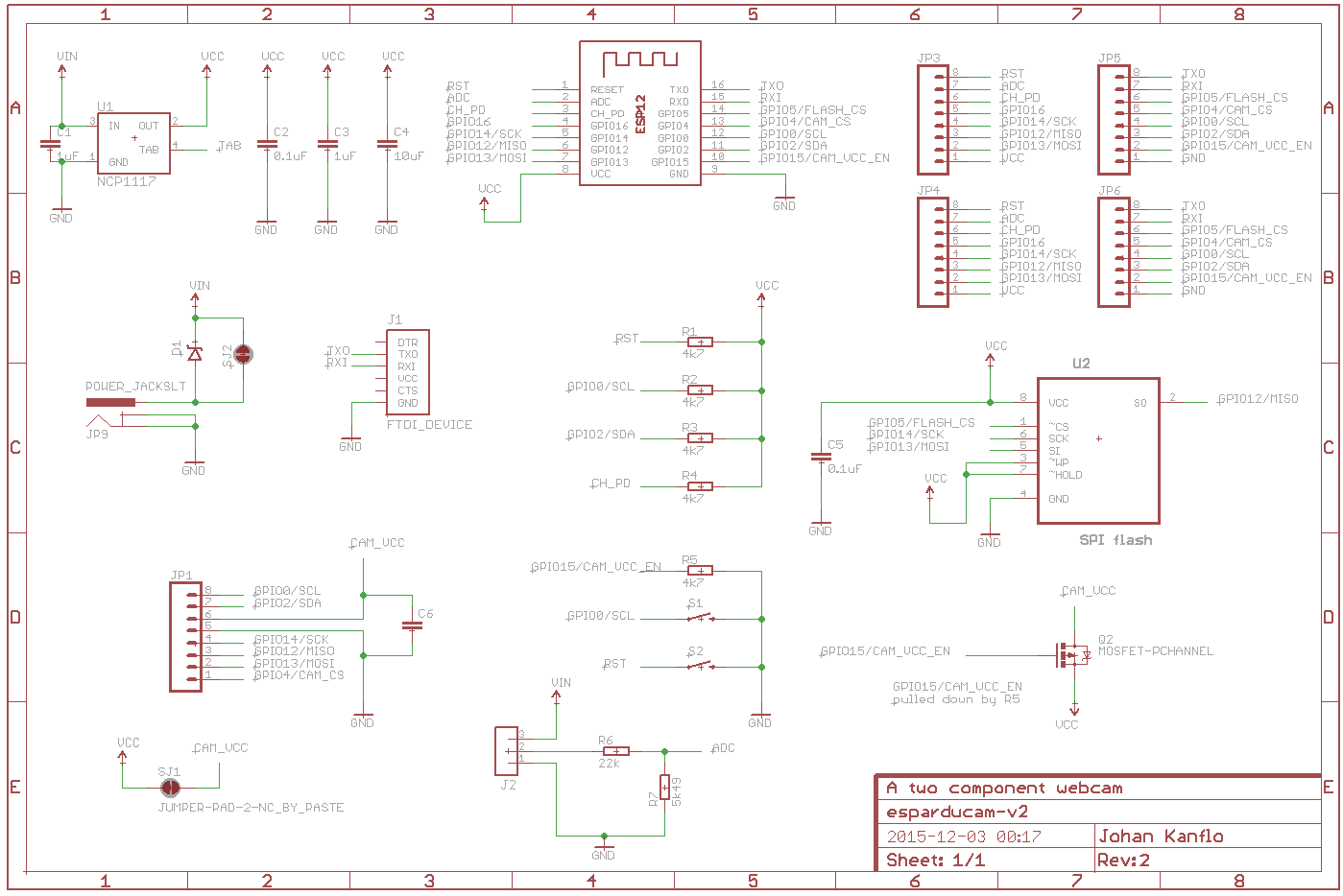
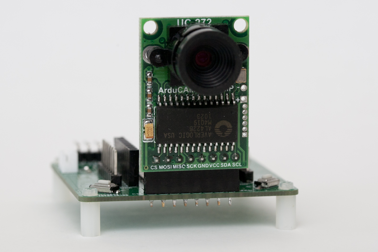
Sometime ago I came across the Arducam Mini which is quite a nice camera module from UCTronics. It is a small PCB with a two megapixel OmniVision OV2640 sensor, an interchangeable lens and an FPGA to do the heavy lifting of image processing and JPEG encoding. Priced at around 24 Euros (lens included) you can easily buy a few without hurting your wallet and combined with an ESP8266 you can build quite a low cost wifi camera. Or several. Because designing and building PCBs is both fun and inexpensive I designed a board to go with the ESP8266/Arducam Mini combo, aptly named the Esparducam. And uniquely named too, try googeling for “esparducam“. Heck, even the domain name is available at the time of writing 🙂
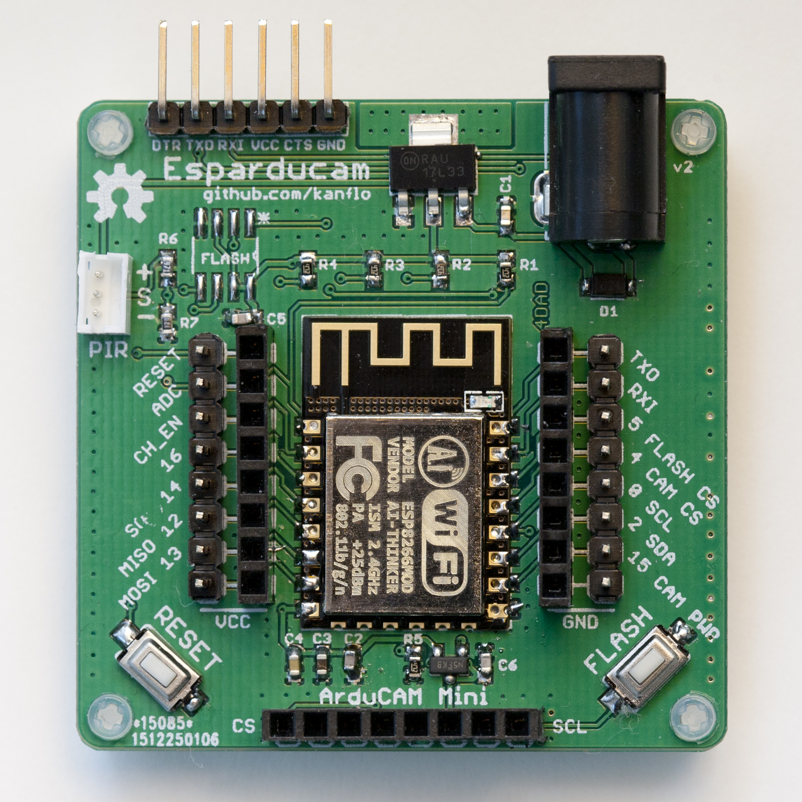
Anyhow. The Esparducam board is a development board for the Arducam Mini module and is quite well suited for ESP8266 development in general.
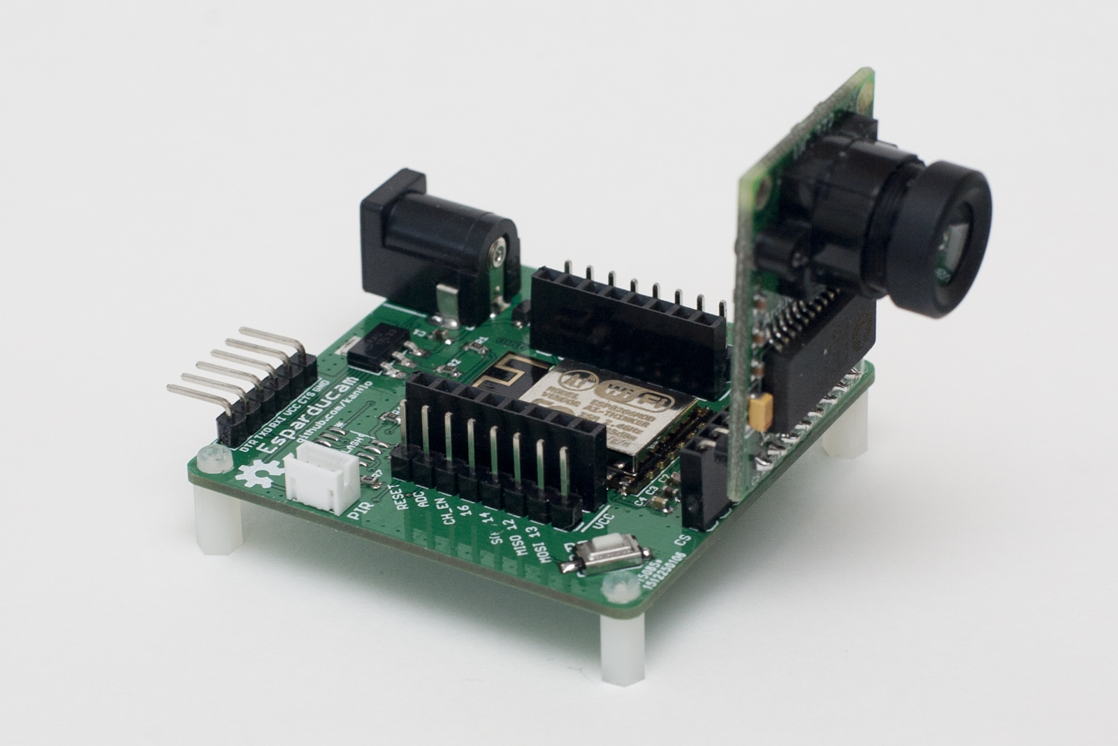
The board is powered through a barrel connector at a minimum of 5V (upper limit untested) and all the IO pins on the ESP8266 are available on pin headers. The double rows are intended for the design of small breakout boards that sit on the inner 0.1″ aligned headers while the outer headers allow for connecting logic analyzers/oscilloscopes and so on. The Arducam Mini module plugs right into the front header and the standard FTDI connector is at the back of the board.
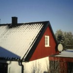
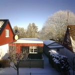
Image quality is, imho, quite decent at this price point, here are a few samples.

An optional SPI flash can be mounted for image storage and you can connect a standard eBay PIR module to the white JST header next to the FTDI connector if you want to build a motion triggered camera.
I am no hardware engineer but if you are and you find any silly design mistakes please let me know.
You can order the Esparducam board form DirtyPBCs and I would love to know if you build one. I plan to build a few for house monitoring, kite photography, reading my water meter and whatever else I can come up with.
The demo application listens to port 80 for HTTP GETs and will capture and return an image. It also has a command line interface on the serial port and the command ‘upload:<ip number>’ will capture an image and upload it via HTTP. A Python script is included that will receive and display the image using your system’s default image viewer. Note that the demo application is just that, a demo application. It does not handle simultaneous clients, errors or anything else that occurs in the real world.
 Lastly a note about the lens. It uses a mount called M12xP0.5 and there are plenty of lenses to choose between. The one included with the Arducam Mini module has about the same field of view as a normal 50mm lens on a full frame DSLR. I would recommend getting a 3.2mm lens or shorter for some more wide angle if you plan to use the module for surveillance applications. The 3.2mm lens (called LS-40136) can focus at a very short distance making it a candidate for water meter reading applications.
I have yet to try the even shorter ones like the LS-20150 at 2.8mm or the LS-40166 at 2.6mm.
The Esparducam turned out so nice it became my preferred ESP8266 development board, why is a different post.
Code and hardware schematics as always on Github.
Pingback: A versatile ESP8266 development board – Johan Kanflo
Pingback: Building a low cost wifi camera - Electronics-Lab
this looks great, arducam on order
Geat! I´ll look forward to build one to test it. Maybe it is the right design for my home survilliance project.
Looking forward to hear about your project. I will compile a BOM for the board shortly.
Any update on the BOM?
Sorry about the delay, here is the BOM with some information about what is optional when building the board.
Hi I am also trying to use the Arduino UNO with ESP8266 for home automation and security solutions could you tell if there any way i can add camera streaming to my project
I was just reading the datasheet for the OV2640 tonight. It has its own JPEG capable compression engine. I wonder if Arducam is using it and just using the FPGA to provide the serial data interface (the OV2640 has a parallel interface for data), or if they are doing compression on the FPGA as well.
Interesting, I haven’t checked the data sheet myself. The sensors I have seen so far just provides raw bayer data and leaves the image processing and subsequent image compression to you.
I have an OV7670 module that I want to try to get working with the ESP8266. I picked it because it was the cheapest available, at less than $4 US. It can spit out various RGB, or YUV/YCrCb formats. No compression though, beyond the chroma subsampling in YCrCb.
I figured if I could acheive a high-bit rate, I could upgrade to something more capable.
It looks like ArduCam may use the FPGA to present a consistent command set and hardware interface across camera modules. In poking through their ArduCam library it doesn’t seem complicated enough to be providing the abstraction in software.
Great idea! I can’t make hardware, how can I buy it?
I do have some spare PCBs that I thought of building and selling. I just need to find out where to go 🙂
Did you try to use it for OCR?
That would be an interesting use case. I tried tesseract on an image of my water meter and it did find the static text on the meter. Image quality is ok for OCR I think and the optics can focus on quite a short distance (~15 cm with the wide angle lens I tried).
I was interested exactly to OCRing meters, but distance 15 cm i’s to far. Did you try to use OV7670 300KP VGA Camera Module? It’s cheaper.
I didn’t know about that one. Thanks! It seems to be using the same optics, there might be an M12xP0.5 macro lens.
Any new on OV7670 300KP VGA?
I had a quick glance at the 7670 and the amount of required IO seem to be too much for the ESP8266. The ESP32 would probably do.
Hello Johan, how did you manage to use tesseract to OCR the meter reading? I keep taking pictures of mine, even turning the picture to black and white, but the text output from tesseract is null. On the other hand, I tried OCRing one .png file from a book page, and it worked perfectly!!! but not for meter´s. Do you have an example picture for me to test on? Thanks!
Nice and clean work! I know this is no webcam but just to get an idea, what kind of “framerate” do you achieve?
Thanks! The frame rate currently is quite poor but then there’s lots of optimization to be made. For instance I read the JPEG FIFO one byte at a time (one complete SPI transaction for each byte image data). There is a streamed mode on the Arducam Mini that would increase frame rate by at least 4x.
This looks awesome! Could you elaborate on what “quite poor” means for the framerate?
You can put up extra boards on tindie and I will be sure to get one.
Great project, thanks so much for sharing.
I too would be interested in buying components for my own projects, specifically how to take and send an image “on demand”, kinda “I’m in the vicinity, gimme a sit-rep.”.
Some thoughts on building battery powered units would be helpful (to me). For me, this almost always boils down to “how do I switch it on, on demand?” “what power usage can it get down to in listening mode?”.
Anyhow, another use-case you might take into consideration when keeping options open for other makers.
Thanks! I just finished a write up about the BOM. Running the Esparducam on battery would be interesting. I guess adding a PIR to wake the ESP from deep sleep and log on to wifi would be the way to go. I have not looked into low power operation of the ESP8266 yet.
Pingback: ESP8266 WiFi Module Design Notes - manton
can you share a link to buy the ESP-Module on ebay
Actually I noted that sellers on AliExpress have a better price, €1.63 compared to €3.00 on eBay. I just search for ESP-12f, sort by lowest price and pick the first seller with many orders and good reputation.
How long does it take to take a picture?
A couple of 100ms. Currently I don’t use the fastest way of reading data from the camera module. I will get back with an exact number when I have optimised the code.
Hi Johan,
Thanks for this great project!!
I got this already running on a NodeMCU and of course
i need to try your project too!
i ordered a few of those boards and can’t wait to start 🙂
Regards,
Johan
Hi Johan,
Question. is there much difference when i use the ESP-14 instead of the ESP-12?
When i mount the components except the ESP module the power voltage is 3.3 V.
But as soon as i mount the ESP-14 the LM1117 is getting extremely hot.
I tried to build two units with exact the same result.
Regards,
Johan
I have no experience with the ’14 but a quick Google turns out it’s not pin compatible with the ESP-12. The ’14 GND pad is in the same location as the ’12 VCC for starters. Do you have an ESP-12?
Hi Johan,
Thanks so much for sharing your project!
I’d like to get your opinion on what I intend to do which is not so far from that …
I’m looking for the cheapest configuration that would allow me to do the following:
1) take a screenshot from any low size camera (low resolution is not a problem) when a tilt sensor is triggered
2) wake up a wifi soc (esp8266 would be the best because of its price) to send the picture to a web site
3) return into deep sleep mode and notify the user (could be done though the web server I guess …)
Any idea of the best configuration to do that? 🙂
Any update on my questions? 🙂
Hi Jep,
Sorry for the delay. You could use a Arducam/Esparducam combo for this but you could of course run everything on a Ras Pi. It depends on your {size, power & monetary} budget.
Regards,
Johan
Hi Johan,
No problem for delay of course!! 🙂
Esparducam is a good idea but it is much too high in terms of budget
I was targeting something like the OV7670 but I’m afraid there are too few GPIOs on ESP8266.
Regards,
Jep
Pingback: Weekend Reads [14th May 2016] | esp8266hints
Hi Johan,
Just finished my build with the ESP-12. Looks much better.
Yes. the ESP-14 is definitly not compatible with the ESP-12.
Now i need a way to flash this baby as my esptool sais it cannot
connect to the ESP8266
Regards,
Johan
Hi. That sounds strange. A few things worth checking, depending on what gear you have. Current consumption, voltage level at relevant pins. I have found that sometimes I need to revisit some ESP12 pads with the soldering iron. Check the GND pad on the ESP. Also check GPIO 0 and 2. Also, you might have a dead ESP12 module. I often find that one out of 10 is a dud. That’s why I always test my ’12s using the pinlet board prior to mounting.
Hi Johan,
I got it working.
The problem was the esptool.py what i use to program
the esparducam. it seems that you have to put the gpio0 to the ground
and power cycle the board. After that it can find the esp8266 and am i
able to program it.
The setup is working good. It is faster as running the cam on a NodeMCU.
Regards,
Johan
Nice project. I’ve not got a board built and am working through the build readme.
fatal: Authentication failed for ‘https://github.com/kanflo/eor-spi.spiflash/’
That wants a user and password?
Thanks! My bad, it’s a typo and should read …/eor-spiflash
That was easy – thanks.
Sorry to be dense, but one more please:
…/esp-open-rtos/common.mk:356: extras/http-upload/component.mk: No such file or directory
Did I miss the easy path to http-upload? Git has so many of them…
Oups again. I updated the read me with
git clone https://github.com/kanflo/eor-http-upload.git http-uploadHi Johan,
Question. Does your code also support the OV5642? I tried that camera
as it has a better resolution as the OV2640 but with the OV5642
cam i only have SPI errors.
Welcome to camera mon. Type ‘help’ for, well, help
% Camera power cycle
scandone
arducam_spi_init
arducam_i2c_init
SPI interface error (got 0xff)!
with the Arducam code there was a bit rotation needed what was done in the SPI.c but i have
no idea how to get that done with open-rtos
uint8_t SPIClass::transfer(uint8_t data) {
while(SPI1CMD & SPIBUSY) {}
// reset to 8Bit mode
setDataBits(8);
SPI1W0 = data;
SPI1CMD |= SPIBUSY;
while(SPI1CMD & SPIBUSY) {}
uint8_t val = SPI1W0 & 0xff;
val = (byte)(val >> 1) | (val << 7); // correction for bit rotation from readbac
k
return val;
//return (uint8_t) (SPI1W0 & 0xff);
}
Regards,
Johan
Hi Johan,
Late reply, sorry. I have not tested the 5642. You should check the original Arducam repository and check why might be missing or different for 5642 support.
Cheers,
Johan
Thanks for this, Just ordered some boards, going to start building some camera’s 🙂
Nice!
Sir,
How is viewing angle of this ? can i use it as car reverse camera. It needs good viewing angle of 170 – 180 degrees to be a reverse camera for the car.
Viewing angle depends on the lens and there are plenty to choose from including fish eye lenses. Frame rate could be an issue though.
Hi, what is the program flash size? nearly full 1MB?
I am thinking if we can use 2 of esp-8266 to connect wifi directly or through a router. One ESP8266 as a surveillance camera sending video 24/7 to another ESP8266 which is storing video to either a sd card or hard drive? Able to do so?
Actually far from half full even. I would go for something with more connectivity for storing video. Perhaps a Pi Zero.
Thanks for your advise. So do you mean use ESP8266 s a surveillance camera sending video 24/7 to another Pi Zero or even a Windows PC which is storing video to either a sd card or hard drive?
You’re welcome. Mind that the Arducam does not produce video but JPEGs, thus you will not get a very high frame rate. It will make quite a good still image surveillance camera though. I plan to use a PIR to detect when to capture.
Thank you very much for this advise on Arducam which now I had realized my mistake. Now I know why Arducam did not reply my second email after I had let them know it is a video project.
Yes, I am also planning to use PIR to start camera with a delay to 30 seconds after PIR had stop detecting motion.
Is ESP8266 has the ability to act as a surveillance video camera with low resolution 480p, 8 frame/s?
It might be able to do 8fps at low resolution. There is still improvements to be made in reading the image from the Arducam sensor.
Thanks for your great project.
Is there a way to order a completed board with full material soldered?
You’re welcome 🙂 I am actually planning on mounting the rest of the PBCs I got from DirtyPBCs and sell them. Stay tuned.
Hello Johan,
I want to make an esp8266 wunderground weather station and would like the Arducam to take a picture and store it to sd card. However, do you know of any way to upload via ftp from the sd card or to have an http address that wunderground can pull the jpeg from? I am actually working with this module, http://www.arducam.com/world-smallest-esp8266-wifi-camera/
Hi Dave. You could have WU pull the image directly from the camera (there is an implementation for that) but it would probably better to have the camera upload the image to a server where WU can request it.
Thanks Johan, this project is on my todo list, i recently saw arudcam makes an all in one camera+esp8266 solution that I will take a look at. http://www.ebay.com/itm/Arducam-2MP-V2-Mini-Camera-Shield-ESP8266-Esp-12F-Nano-Evaluation-Kits-/182303551819?hash=item2a7223714b:g:gUYAAOSwqfNXnrKR
Unfortunately the lens is not interchangeable on that board. I have a smaller Esparducam board for use with the Arducam in the works.
Johan, good point i didn’t think of the lense. I only want to take pictures of the sky to go with the weather station data. In your opinion would the standard 60° lense do the trick, seems like it should be good enough for my purposes. Thanks.
60° should be enough, according to Wired the FOV on the iPhone 6 camera is 63.54° for comparison.
Hi Johan,
Do you know what the upload rate is per image through WiFi and from ArduCam to the ESP?
Also – I can’t find much information regarding buffer size and SPI communication speeds.
Thanks!
Hi Nethanel, I have not measured the frame rate but its nowhere close to 24fps 🙂
Johan,
I know this has been 2 years, but what do you think of using an esp32? with the dual cores, could it maybe capture several stills quickly (making a lo-fi movie possible if stitched together on a PC, etc.)?
I have an idea for sleeping an esp32 (on battery), then waking up when activity on a bird feeder (maybe simple ‘radar’ module) to take a few snaps when there is motion.
Thoughts?
P.S. for those unfamiliar, the esp32 can be reconfigured, but out of the box one core is strictly I/O (BT, BTLE, WiFi, …) while the other is strictly your program.
TIA!
I think it’s an excellent idea. Being a tad bit late jumping on the bandwagon, I am about to shift my WiFi efforts to the ESP32. A camera project would be a good start.
Hi Johan,
Have you seen the “ESP32-CAM Development Board (with camera)”? I purchased one, but it took months to receive it and Seeed are out of stock (www.seeedstudio.com/ESP32-CAM-Development-Board-with-camer-p-3153.html).
I good start would be :github.com/bitluni/ESP32CameraI2S
and github.com/bitluni/ESP32Camera by the funny YouTuber Bitluni/
Regards,
Peter
Thanks, I have seen it and it’s on my shopping list. My new year’s resolution is to never buy stuff until I have the time to play with them so Seeed will have plenty of time to restock 😉
Johan,
That is a horrible, cruel, and inhumane resolution that if adopted could save countless marriages.
😀
First of all, congratulations for the design!
I’m doing a project that uses the camera and an hc-sr04 sensor. I wonder if you could create a pcb using the esp8266 or esp32 using these sensors. Give me a budget if possible.
Hello Johan,
I would like to ask what is the focal distance of the lenses you mentioned on the article?
I would like to buildone board for water meter reading applications.
Thanks