Some time ago I found the DPS5005 while browsing AliExpress for programmable power supplies. To be honest, I dismissed the ‘5005 since it was not a complete product. Then HAD wrote about it in december last year and after watching YouTube user @iforce2d’s video I just had to get one. The overall impression was quite good but the software was a bit cluttered and the DPS5005 could not be instrumented via a serial port (or wifi). Looking closely at the sandwich PCB design I noticed the DPS is powered by an STM32, which is pretty much what I expected. And so begun the OpenDPS project, a free firmware replacement for the DPS5005 and friends.
This write up of the OpenDPS project is divided into three parts. Part one (this one) covers reverse engineering the stock firmware and could be of interest for those looking at reverse engineering STM32 devices in general. Part two covers the design of OpenDPS, the name given to the open DPS5005 firmware. Part three covers the upgrade process of stock DPS:es and connecting these to the world. If you only want to upgrade your DPS you may skip directly to part three.
Reverse engineering the DPS5005
The reverse engineering of the DPS5005 can be summarised as “bring up of the STM32 based DPS5005 hardware and writing an application for it”. This is pretty much my day job but I always have the hardware schematics and the hardware design engineer at hand. This time, obviously, I had neither which was a bit more challenging. So where does one start? Looking at the PCB, I quickly found the serial port. That was a dud, completely silent. Fake port! I later realised the DPS5005 stock firmware does not even initialise the serial port. The STM32 is covered by the TFT display, which in turn is soldered using eight pins. As I did not have the time to play with iron and solder wick I resorted to a metal saw and promptly sawed the TFT display off (please note this is not the unit in the pictures below).
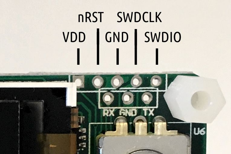
Warranty voided, oh there actually was none to begin with. Having the STM32 in the open quickly allowed me to identify the five test points at the top of the PCB, the expected SWO trace port. But had the producers locked the SWO port when flashing the firmware? Luckily, no.
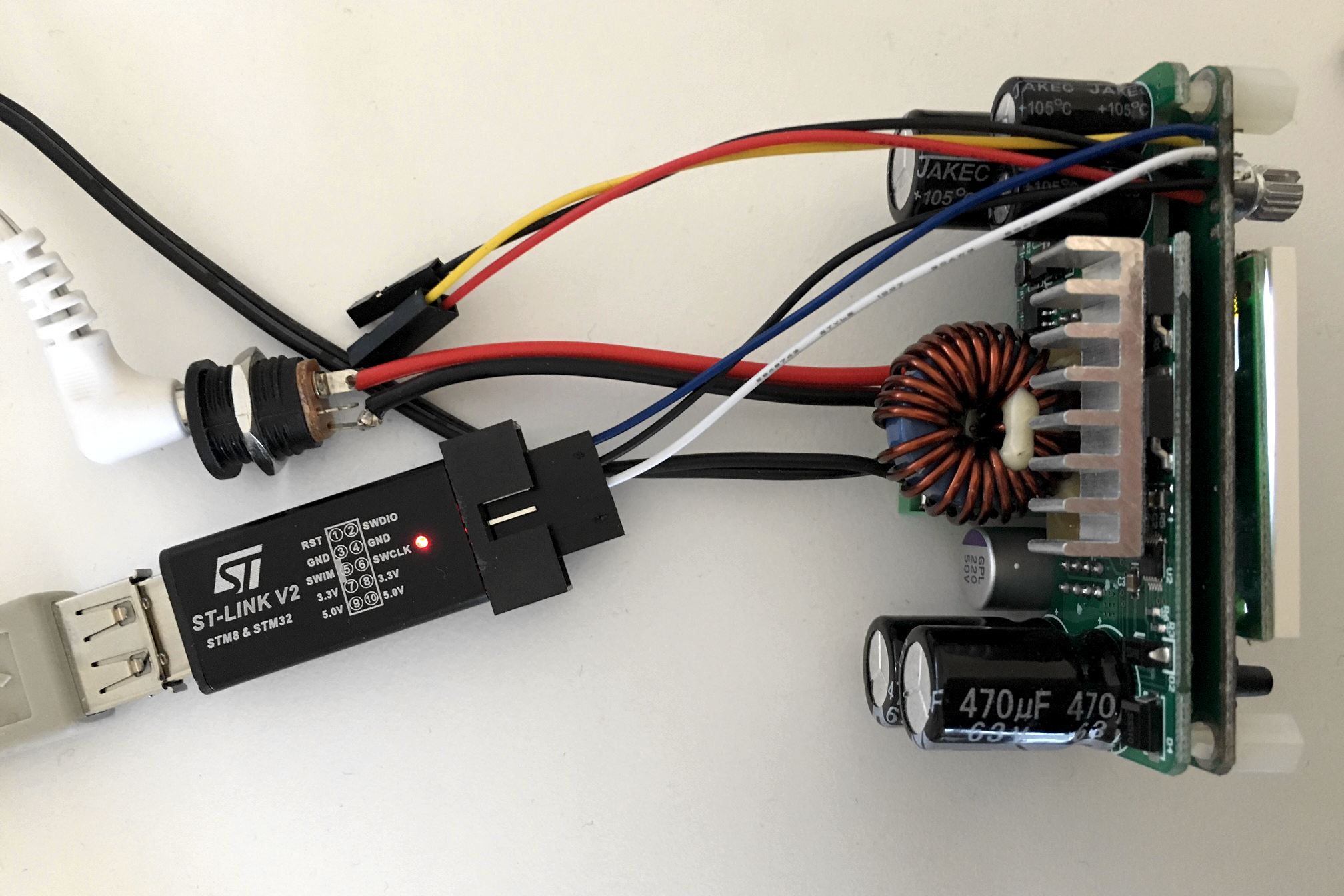
After some soldering, connecting an STLink clone and selecting an appropriate OpenOCD configuration for the STM32F100, I had a go at it:
% openocd -f interface/stlink-v2.cfg -f target/stm32f1x.cfg
GNU ARM Eclipse 64-bits Open On-Chip Debugger 0.10.0-dev-00498-gbbfb673 (2016-10-28-19:13)
Licensed under GNU GPL v2
For bug reports, read
 http://openocd.org/doc/doxygen/bugs.html
Info : auto-selecting first available session transport "hla_swd". To override use 'transport select <transport>'.
Info : The selected transport took over low-level target control. The results might differ compared to plain JTAG/SWD
adapter speed: 1000 kHz
adapter_nsrst_delay: 100
none separate
Info : Unable to match requested speed 1000 kHz, using 950 kHz
Info : Unable to match requested speed 1000 kHz, using 950 kHz
Info : clock speed 950 kHz
Info : STLINK v2 JTAG v17 API v2 SWIM v4 VID 0x0483 PID 0x3748
Info : using stlink api v2
Info : Target voltage: 3.245093
Info : stm32f1x.cpu: hardware has 6 breakpoints, 4 watchpoints
Yay! Next I connected to OpenOCD to examine the target:
% telnet localhost 4444

> halt
> stm32f1x options_read 0
Option Byte: 0x3fffffe
Readout Protection On
Software Watchdog
Stop: No reset generated
Standby: No reset generated
User Option0: 0xff
User Option1: 0xff
So “readout protection” is enabled which mean you cannot read the firmware from flash. Not a biggie as I was not interested in the stock firmware in itself, only what it controlled. So what would be needed to create the OpenDPS firmware?
- Learn how buttons and other IOs are connected.
- What STM32 peripheral drives what function?
- Controlling the output voltage (controlled by the DAC?)
- Current limiter (maybe ADC?)
- Measuring input and output voltage (definitely ADC)
- Dimmable TFT (not needed 🙂
- Write a TFT driver
To assist, I created a Python script (ocd-client.py) connecting to OpenOCD for dumping various STM32 device registers. Eg, by dumping the entire DAC register area I could determine the DAC was in use. The buttons I could identify by dumping the GPIO input registers, pressing the button and dumping the registers again. The entire GPIO setup can be recreated by this script and I learned the output voltage really is driven by the DAC. The TFT backlight is driven by timer 4 and the output current, input voltage and output voltage are measured using ADC1 on channels 7, 8 and 9. The 1.44″ TFT is an ILI9163C and I used @SumoToy’s driver for this. The SPI select pin for the display is grounded which is a clever way of saving one pin for designs where there is only one device connected on the SPI bus. Additionally, the display does not use the MISO pin. The most important thing now was how to control the DAC to set a desired output voltage, how to interpret the ADC1 values measuring the output voltage, current draw and input voltage. Normally, one would look at the schematics to figure out what an ADC reading means but in this case I had to reverse engineer that. I simply connected a multimeter, tried a few settings on the stock firmware, observed the ADC1 reading and plotted the result. Next, I created a simple application using the lovely libopencm3 and tested in on a “Bluepill” before wiping the DPS5005. Telnetting to port 4444 again I tried:
> reset halt
> flash erase_address unlock 0x08000000 0x10000
Device Security Bit Set
stm32f1x.cpu: target state: halted
target halted due to breakpoint, current mode: Thread
xPSR: 0x61000000 pc: 0x2000003a msp: 0x20000800
stm32x device protected
failed erasing sectors 0 to 63
Failed! Hmmm, let’s do a power cycle, restart OpenOCD and try that again.
> flash erase_address unlock 0x08000000 0x10000
device id = 0x10016420
flash size = 64kbytes
erased address 0x08000000 (length 65536) in 0.094533s (677.012 KiB/s)
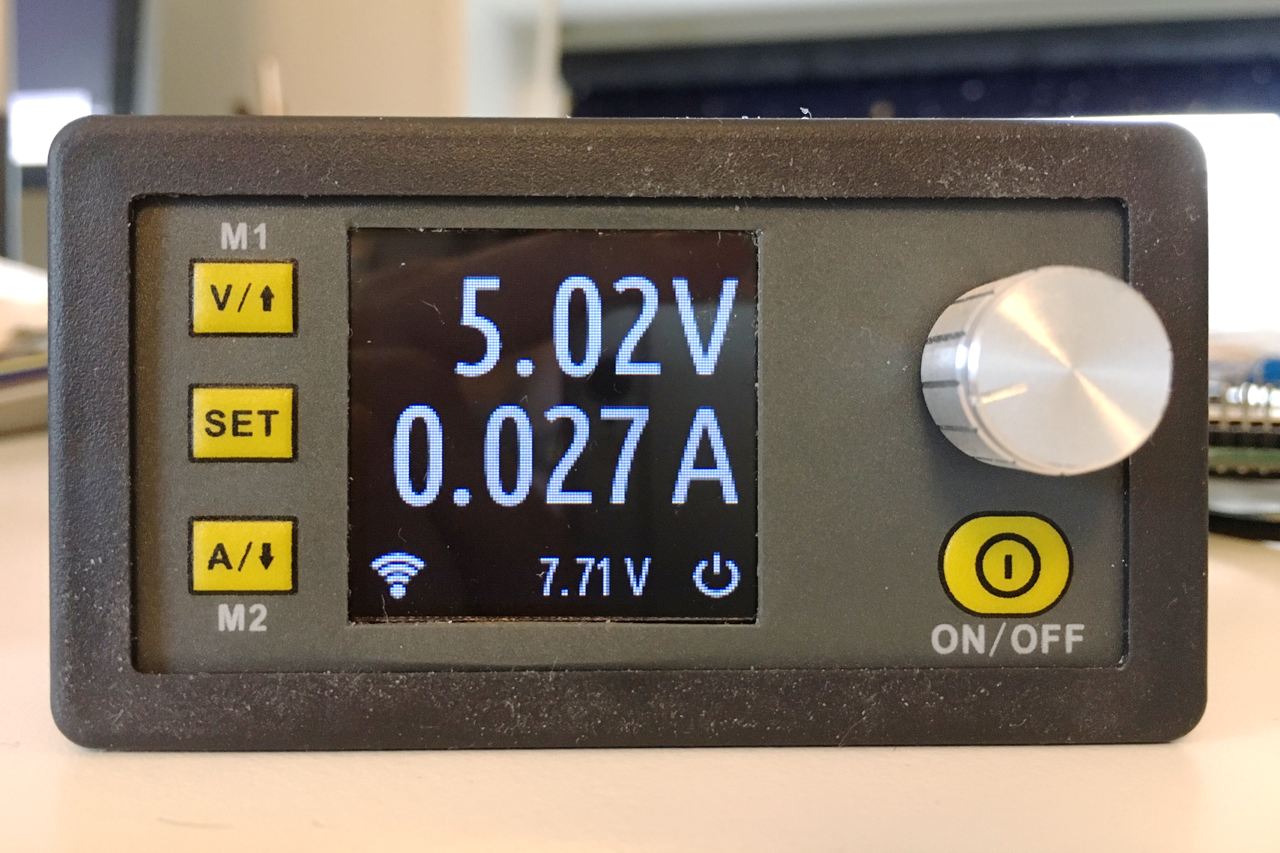
Now that’s better! I am not sure why it fails the first time, it did so on both my units but succeeded on the second attempt. A simple ‘make flash’ and the display showed my test pattern and the power output was at the expected 5V. Mission, partly, accomplished! I could reflash the DPS5005 and control the voltage setting. Time to write a proper application. More in part two.
Any thoughts on the other variants of this power supply? I was looking at the DPS3012 http://www.ebay.com/itm/401180684557 and thought it might be compatible
I have none to test but expect the ‘3012 to work.
I bought one, we shall see
Hi Evan,
Did you try to flash DPS3012? Does it has the same HW/pinout ?
I will update with my documentation of what the 3012 is later today or this weekend. It is somewhat different and if I’m honest I have not tried programming it yet. I was going to root around in the code looking for voltage and current limits before actually flashing something, but I got distracted by some IoT stuff.
Pingback: Open Source Firmware for DPS5005 Power Supply - Hacked Gadgets – DIY Tech Blog
Very cool project.
How about the DP50V15A any changes of getting it to work on that one?
I’m also interested in this as I have a DP30V5A. I love the module but the user interface is deeply odd and I keep pressing the wrong button. Setting a preset is particularly difficult and I have to refer to my crib sheet every time.
I would expect it to work but have none to test on. Be brave 🙂
Pingback: Open Source Firmware For A Cheap Programmable Power Supply | Hackaday
Awesome work! Thanks for the great write up
I’ve been looking around to see if anyone has open source firmware for this device and finally found your post.
I use a lipo pack to power this little DPS gadget. I wanted it to be able to turn off itself when the input voltage is lower than a set threshold or if the mAh has passed some set numbers. I’ve not looked at your codes, but I think it should be easy to add this feature.
Thanks! It should be very straight forward to add this check in the ADC IRQ handler and post an event to the main loop to update the UI.
Pingback: 0. Что не так с DPS5005? | zhevak
Is there maybe some kind of a protocol definition for RS-232 or do I have to reverse engineer this from your Python script?
I would like to steer them from a microcontroller and so i want to have a communication directly without python.
Great work! I just ordered some more after I found this article today!
You should be able to reuse protocol.c, the specification-of-sorts is in protocol.h.
Hi, I’m a fan of your work.
I want to load openDPS when I repair my module.
The two transistors below the aluminum heatsink burned.
Do you know what transistors are? Do you have any schematic of that PCB?
thank you very much
Hi Alejandro. Sorry but I don’t have any schematics. My suggestion is to read what’s printed on them and google. A lot of the components seem to be Chinese which makes sourcing a bit hard. Chances are you might find them on e.g. AliExpress.
Hi Johan,
thanks for sharing your knowledge, i follow your instructions…
at one point i dint not need a power cycle .. following worked for me:
> reset halt
target halted due to debug-request, current mode: Thread
xPSR: 0x01000000 pc: 0x080001cc msp: 0x20000800
> flash erase_address unlock 0x08000000 0x10000
device id = 0x10016420
STM32 flash size failed, probe inaccurate – assuming 128k flash
flash size = 128kbytes
Device Security Bit Set
target halted due to breakpoint, current mode: Thread
xPSR: 0x61000000 pc: 0x2000003a msp: 0x20000800
stm32x device protected
failed erasing sectors 0 to 63
> flash erase_address unlock 0x08000000 0x10000
Device Security Bit Set
target halted due to breakpoint, current mode: Thread
xPSR: 0x61000000 pc: 0x2000003a msp: 0x20000800
stm32x device protected
failed erasing sectors 0 to 63
> reset
> flash erase_address unlock 0x08000000 0x10000
Target not halted
failed setting protection for blocks 0 to 63
> reset halt
target halted due to debug-request, current mode: Thread
xPSR: 0x01000000 pc: 0xfffffffe msp: 0xfffffffc
> flash erase_address unlock 0x08000000 0x10000
erased address 0x08000000 (length 65536) in 2.653152s (24.122 KiB/s)
>
I would like to install this on my DPD5015, would it be possible for you to provide the already compiled firmware bin and/or elf’s
Can you port it to the DPS5020 as well?
It would be super awesome!
The DPS5015 is supported so the ‘5020 should work out of the box. I have none to try but if you are feeling brave, please share the result 😉
it would be grate to have a tutorial how to modify it
hello, the product works.
I have the BT module, is it possible to have a notification on the phone when the current goes to 0?
or another possibility? I need to know because the material is far away, it’s for surveillance.
thank you
The short answer is ‘yes’. You would need a simple Python script talking to the ‘DPS (not necessarily using BT which just complicates things) using dpsctl.py and sends a push notification using eg. pushover.net
hello, thanks for your quick reply.
I read the github on dpsctl.py.
it’s too complicated for me, I do not know the python language: /
(I practice arduino, esp8266).
I do not have the skill to change the firmware and load it into the dps5005. : /
collar do more simply if it’s possible?
Thank you for your help
have a good day
ps exuse me for my english, thank you google 🙂
I think the way forward for you is either to learn coding using Python or find someone to implement the solution for you. The former is more fun 😉
Hello,
ouupps it’s not the dsp5005 it’s the dph5005.
Thank you for your help. I will see.
When I pulled the LCD off my DPS it has a STM8S003 MCU on it and not a STM32. I’m not sure which DPS I have since I’ve had it for some time and there is no marking on the unit itself.
I assume your code won’t work with this since this unit is smaller and lower powered CPU?
Interesting, you wouldn’t have the model in e.g. a confirmation email from the place of purchase? Would be sad if the ‘5005 & friends went STM8.
I was wondering if it would be possible to control the DPS5020 just from the PC (via the PC software and a USB link) without connecting the small Control/Front Panel at all?
What about DPH5005? Can it work with OpenDPS?
It could be so as it looks quite similar to DPS5005.
Greetings,
Please indulge me this one question.
How would you go about connecting the DPS 5005 UART to a UART on an Arduino Mega2560?
Thanks, Al.
Connect DPS DPS TX, RX to ‘2560 RX, TX (note the order) and connect GND on both.
Thank you for your response.
I”‘ve discovered that I should use a Logic Level Converter to connect the 3.3v logic levels of the DPS UART to the 5v Arduino Mega 2560 UART.
The Arduino Due has however native 3.3v logic levels. As well as the Atmega 2560 Mini Pro. The latter providing the needed additional 2 UARTS’, Which is likely to be my choice for this project.
Thank you for your assistance. I will report my results.
Can someone tell me how to calibrate the output?
I measured a 0,0534V per 1V difference in the output. OpenDPS for examle is set to 5V, the Output is 5V-(5*0,0534)=4,733V, which is shown as actual output voltage if active and multimeter.
A Vout set to 25V, active output measures 23,66V (multimeter and actual voltage in Display)
I have a dps3012 and i am waiting for a dps5020.
i will test both! I hope someone will help me to unbrick if its incompatible.
I’m working on dps5005 and in constant voltage mode when I go to set the voltage below 3.3(volts) the device turn off but I want to set it at 0v.
Can anyone help me in this regard