This is the third article about hacking the DPS5005. Part one covers the reverse engineering of the DPS5005 and part two covers the design of OpenDPS.
April 14th 2017 update: is has been verified that OpenDPS can push 5A. Thanks @johannes!
June 9th 2017 update: added a note on saving the STM32 peripheral settings before wiping the internal flash.
August 31st 2017 update: updated article with the new boot loader and a note to test your device prior to unlocking.
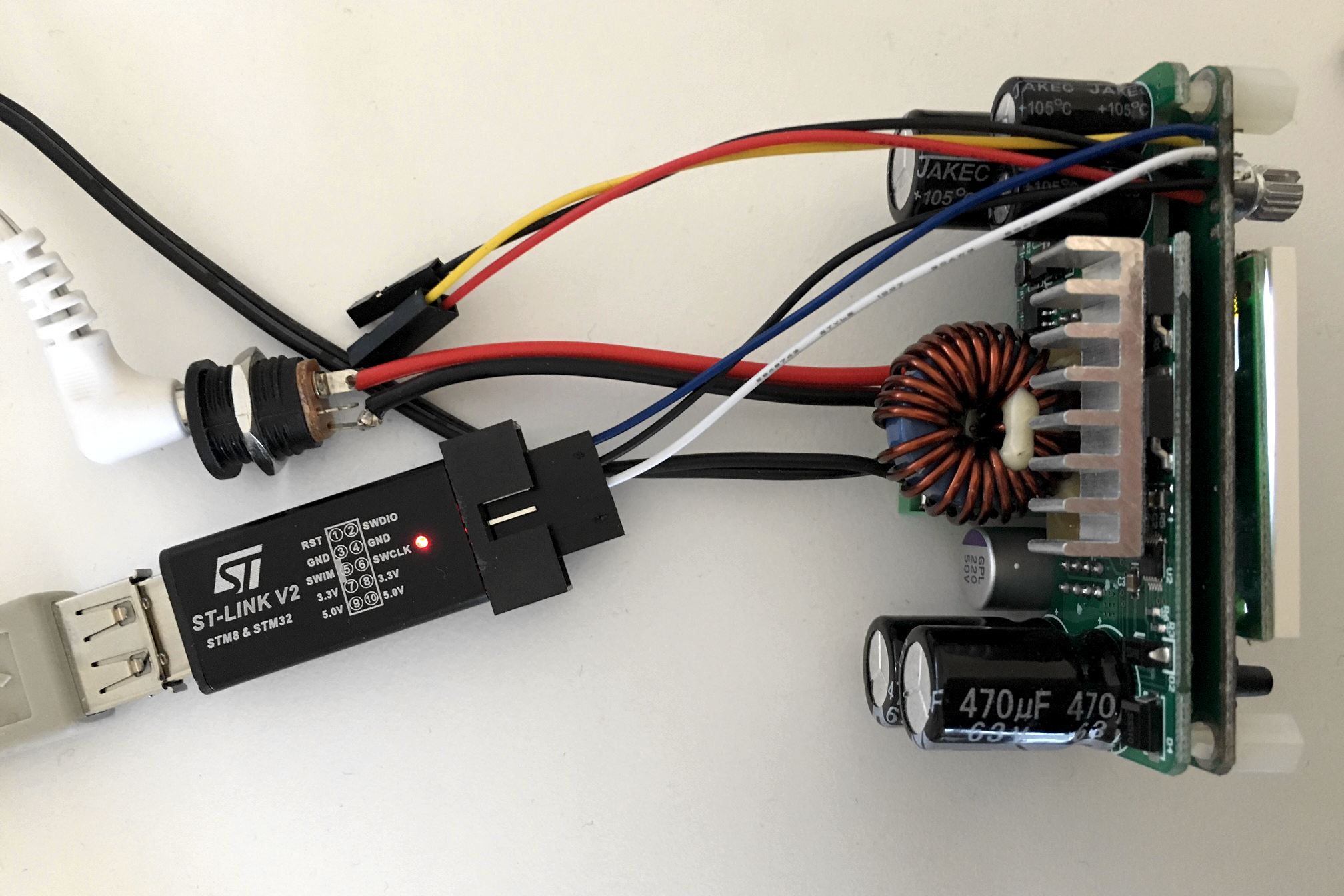
Although this guide is written for the ‘5005 it should work for the entire DPS family but I only have 5005s to test with. Before we begin I should mention that the stock firmware will be gone permanently. As readout protection is enabled on the STM32, the FW cannot be extracted and I have no source for it. Additionally, I take no responsibility if you destroy your DPS. That said, let the fun begin. You will need a DPS5005 (or similar), an STLink clone and some wire. Either you solder the wire onto the DPS or you can use female-male dupont wires for flashing.
Teardown
First you need to remove the PCB from the (semi) housing. Use a small flat screwdriver to prey the PCB loose from the retaining flaps.
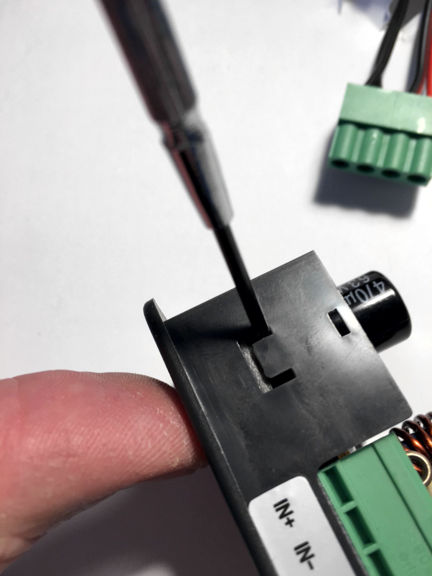
Be careful not to break the retaining flaps (not that they’re fragile, but still). They are very much needed for holding the front panel in place when you press the buttons.
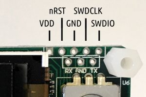
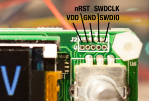
If you have an older version (below left) you can solder some AWG26 wire onto the SWO and UART ports. It is advisable not to solder pin headers as there is limited room inside the housing. I added dupont jumper housings at the end of the cables to aid in connecting them to the STLink clone and FTDI ditto. Hint: make the cables “stretch” backwards, from the display. For newer versions (below right) the 1.25mm JST-GH there is little room for the SWD wires. As a bonus, you need not solder the UART cables in case you bought one of the “communications versions”.
If you do not want to solder (and do not want any remote control) (and have steady hands) you could connect three female-male dupont cables to the STLink clone and hold them pressed against the DPS while flashing.
Building OpenDPS
With that in place you should install OpenOCD and an ARM GCC toolchain. For GCC, Launchpad is a good place to start. For OpenOCD, YMMW. If you are on macOS you can find OpenOCD here (it installs as /Applications/GNU ARM Eclipse/OpenOCD/0.10.0-201610281609-dev/bin/openocd). With the tools in place you’re ready for the next step.
git clone --recursive https://github.com/kanflo/opendps.git
cd opendps
make -C libopencm3
make -C opendps
make -C dpsboot
Flashing
Next you need to unlock the internal flash of the STM32 before flashing (which causes a complete erase). Start OpenOCD:
cd openocd/scripts
openocd -f interface/stlink-v2.cfg -f target/stm32f1x.cfg
You will receive a few lines of output ending with “Info : stm32f1x.cpu: hardware has 6 breakpoints, 4 watchpoints” if the connection was successful.
Please note! Before you unlock and erase the STM32 flash, you should make a dump of the STM32 peripheral settings of your stock DPS firmware. The DPS hardware might change at any time and if you flash OpenDPS and it does not work because eg. the GPIO pin enabling output power was changed, things get difficult. The ocd-client.py script will assist you now that OpenOCD is running. Please note that OpenOCD might interfere with the stock firmware. When you connect, the stock FW might lock up. First, power on the DPS and make sure the power output is disabled but set to e.g. 5V, start OpenOCD and type:
./ocd-client,py all > 5V-off.txt
If needed, restart the unit (and OpenOCD), enable power output @ 5V and type:
./ocd-client,py all > 5V-on.txt
Rinse and repeat for one or two more voltage levels. Check the log files, there should be no lines saying “Parsing error”. If your OpenDPS does not work, these files will enable me (or someone else, remember this is open source you 😀 ) to pinpoint the problem. Additionally, you should test the device before unlocking it. Enable power, connect something and verify that your unit actually works.
Now let’s wipe that flash. In another terminal:
telnet localhost 4444
and type:
reset halt
flash erase_address unlock 0x08000000 0x10000
You will probably get the following, ending with an error:
Device Security Bit Set
stm32f1x.cpu: target state: halted
target halted due to breakpoint, current mode: Thread
xPSR: 0x61000000 pc: 0x2000003a msp: 0x20000800
stm32x device protected
failed erasing sectors 0 to 63
Keep calm. Restart OpenOCD, toggle power on the DPS and try again. This time you should see:
erased address 0x08000000 (length 65536) in 0.094533s (677.012 KiB/s)
Time to flash (flash the app first, then the boot loader):
make -C opendps flash
make -C dpsboot flash
The last two lines should read:
** Verified OK **
** Resetting Target **
and your DPS5005 is now an OpenDPS 5005.
Congratulations! If things went south somwhere, feel free to ask for help in the comments below.
From here you can use the OpenDPS as a stand alone device, control it via a serial port or control it via wifi by connecting an ESP8266.
Short User Manual
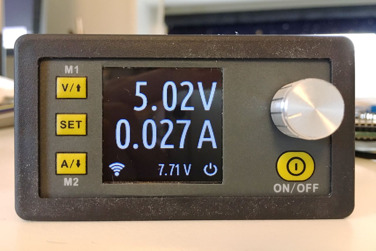
When you power on your OpenDPS, the current voltage and current limit settings are displayed and the power output is always disabled. Pressing ON/OFF will enable power output and the display will now show the measured output voltage and the measured current draw. If the screen flashes once and goes back to displaying the voltage/current settings, the over current protection kicked in. Press ON/OFF again to disable the power output.
Press the SET button to go into editing mode. Press the V and A buttons to move between the voltage and current settings. Press the rotary knob to step sideways and turn the knob to change the values. Press SET again to exit editing mode.
Press and hold the knob for two seconds to lock the keys, long press again to unlock. A long press of the SET key will invert the display.
When your OpenDPS starts it will wait for a wifi connection from a connected ESP8266 and the wifi icon will flash at 1Hz. If it does not get a wifi connection, the wifi icon will be turned off after 10 seconds. If there was an error connecting to your wifi network, the wifi icon will flash at 4Hz.
Remote Serial Control
If you soldered wires to the UART port, connect an FTDI adapter and try the dpsctl.py tool:
dpsctl.py -d /dev/tty.usb.yourdevice --ping
The TFT should flash once as a visual indication. If you get ‘Error: timeout talking to device’, check if you swapped RX and TX and/or forgot to connect GND.
The port setting can be set in an environment variable
export DPSIF=/dev/tty.usb.yourdevice
After setting the DPSIF variable, you can try setting the output voltage to 3.3V:
dpsctl.py --voltage 3300
enable the output:
dpsctl.py --power on
check the measurements:
% dpsctl.py --status
V_in : 7.71 V
V_set : 3.30 V
V_out : 3.32 V (on)
I_lim : 0.100 A
I_out : 0.040 A
% make -C opendps bin
% dpsctl.py -d /dev/ttyUSB0 -U opendps/opendps.bin
make clean ; make WIFI=0 flash
Remote Wifi Control
For wifi control, any good old ESP8266 board with the UART exposed will work. Connect GND, RX and TX, build and flash esp8266-proxy (don’t forget to set your wifi credentials) and you should be good to go.
git clone --recursive https://github.com/superhouse/esp-open-rtos.git
export EOR_ROOT=`pwd`/esp-open-rtos
echo '#define WIFI_SSID "my ssid"' > esp-open-rtos/include/private_ssid_config.h
echo '#define WIFI_PASS "my secret password"' >> esp-open-rtos/include/private_ssid_config.h
cd /path/to/esp8266-proxy
make && make flash
Note that you currently cannot use the master branch on the main ESP Open RTOS repository as my PR for a function needed for multicast has not been merged yet.
When your OpenDPS has connected to your wifi network, try the ‘scan’ command to find out its IP number:
% dpsctl.py --scan
172.16.3.203
1 OpenDPS device found
Next try pinging it:
% dpsctl.py -d 172.16.3.203 --ping
The TFT should flash once as a visual indication. If you get ‘Error: timeout talking to device 172.16.3.203’, check if you swapped RX and TX. The dpsctl.py tool has the same functionality over wifi as well as the serial port.
Sadly, you cannot power your ESP8266 from your OpenDPS. The VDD pin next to the SWO port is connected to U4 (under the TFT), an MD7133H 3.3V regulator which only provides a measly 30mA (yes, thirty). Additionally, this regulator is powered by U3 (on the backside, next to the screw terminal) which is an XL7005A supplying 400mA @ 5V which could be a bit over the edge for a power hungry, cold booting ESP8266.
Todos
There are a few todos in the code but overall OpenDPS should be stable for everyday use.
That’s it, have fun hacking your DPS5005!
This has truly been an interesting series of articles to read. As I come from the hardware design side I often find what you software guys do seems like magic. Thanks for laying out clearly. I really enjoy reading your blog. Thanks for sharing it.
Thanks for the kind words and thanks for reading. I can tell you the feeling of magic goes both ways 🙂
Is it possible to add a compiled Hex file of the build to your Github for those of us with limited software skills?
Yes it is: precompiled elf & bin.
Awesome job, please provide precompiled elf & bin without wifi as well. thanks before
Thanks. Time does not permit compiling and releasing the STM32 binaries, especially since building these are very easy given the ARM support of gcc.
Hi Johan.
Excellent hack. You link to the compiled code goes 404.
I don’t have the tool-chain or the knowledge to do any of these. Could you update the link?
Thanks again.
Could you please make the pre-compiled hex available again? This would make it so much easier for people who have nothing set up for that kind of thing.
Thanks
I did find a very interesting item but I wanted to ask if it was possible via software to vary the reference current from 5A to a higher amperage by changing some power parts. Could you help me with this mission?
openocd -f interface/stlink-v2.cfg -f target/stm32f1x.cfg
This command is not give me the output like mentioned above it give me error any configuration is required ?
I used STM32 clone
Fantastic effort! If I might make a suggestion – this would be even better if it could tie into sigrock: https://sigrok.org/wiki/Supported_hardware#Power_supplies
Being able to remotely control and read values from a DC power supply is crazy handy when testing devices to optimize for power utilization. I have this very supply sitting on my desk, so I guess it’s time to crack it open and get to hacking! Thanks for sharing this work.
Thanks! I guess the PUSs all talk SCPI which would not be that difficult to get into OpenDPS. Besides the wifi/serial control there is a build option for command line support (make COMMANDLINE=1) which could serve as a starter for SCPI support.
Maybe it is an overkill for you, but you can use my SCPI library for this task https://github.com/j123b567/scpi-parser
Thanks, will look into it if I find the time for a SCPI feature.
Do you think it is possible get a “chart” on the Display of the Ampere ?
Would be nice to have a chart over the last maybe 5 to 10 seconds.
That would be a nice addition. The display has scrolling support which would improve the graphics performance.
I am looking on ebay to buy one of these things now 🙂
Can programming be done via the Bus Pirate? or Bus Blaster?
Thanks!
–Aaron
I like the detailed write up.
I have no experience with neither the Pirate nor the Blaster. A €2 STLink v2 clones works like a charm though.
As the DPS is rated as 50V@5A => 250W.. Can it output 12V@10A => 120W?
The DPS5015 should be able to do that.
This is fantastic, thank you! You can use a WeMos, which has an integrated LDO, to connect the ESP to the 5V rail. If you need something smaller, I made a board that’s about half the size of a WeMos and also includes an LDO (no USBserial chip, though):
https://github.com/skorokithakis/tiny-ESP8266-breakout
Thanks! I have a bunch of small ‘8266 boards myself but others may find the WeMos, or your board, a perfect match.
do you still have the original firmware? i upgraded to your’s but forgot (got carried away) to back the original one up. I plan on extending your firmware to support most things the original FW had but in the mean time i need the thing to test my gadget 🙂
Anyways great work!!!
Sadly the original firmware can’t currently backed up because the chip has the read out protection set. Johan mentioned this in his blog post
Thanks @Leonard! And thank you @Jon, it’s nice when one’s blog has enough readership to help one another 😉
What’s are the main advantages over the stock firmware?
Openness and instrumentation.
One of the most obvious change is that the display is much cleaner with the custom firmware. Beside that, it appear that it will allow you to control it from serial and wifi (if you connect an esp8266). Most of the change can be found in part two of the article.
Is it possible to add a compiled Hex file of the ESP8266-Proxy, in my case for a ESP8266-01, to your Github for those of us with limited software skills?
The included binary should work as there is no difference between the UART pins on the ESP-01 and the ESP-12F I use. Could you please try?
I can not find any firmware for an ESP8266, only the opendps.bin.
In which directory I must look?
Your ESP comes preloaded with the firmware so no need to do anything with it.
Ah, sorry. The ESP8266 FW has been added to master.
Thank your for the excellent work 🙂
I’ve just flashed my DPS5005 with OpenDPS. Testing with a 12 ohm power resistor, I can’t get it to output anything more than ~0.32A. If I set voltage to 6V and current limit to 0.7A, the output drops down to ~3.95V/0.32A once I turn it on. Is this expected?
Thanks! That seems like an unwanted feature. Could you try two things? First, check the voltage reading with open terminals? Second, verify the readings with a multimeter? I am thinking it could be an issue with the ADC readings.
Hi, with open terminals the voltage reads 6V. The current reading looks correct when measured with a multimeter. Will check voltage reading later today with the resistor connected.
Multimeter gives 3.7V and 0.31A with resistor connected.
That is very strange indeed. The only time I have seen voltage drop is when shorting the terminals. You didn’t happen to test before reflashing your ‘5005? Oh, and what is the input voltage and what is the rating of your power supply?
Unfortunately I never tried the thing before reflashing, so no idea if it’s caused by OpenDPS.
Power supply is 12.4V (old PSU) rated at 18A/432W.
Any debugging tips for troubleshooting further?
Wow, that ought to provide enough juice. Could you try with something drawing less current? An LED or an Arduino? Do any components on the ‘5005 feel warm when the resistor is connected?
An LED seems to work fine – ‘5005 is stable at 6V with 0.013A current draw. Nothing seems to be running hot with the resistor connected.
Could you try with the resistor and vary the voltage from 1V to 6V? As you get 6V with the LED (and open terminals) the DAC conversion is working but somehow the ‘5005 is unable to provide enough juice when 500mA is drawn and chokes.
1-4V seems to work:
1V: 1V 0.08A
2V: 2V 0.16A
3V: 3V 0.24A
4V: 4V 0.32A
5-6V does not:
5V: 4V 0.32A
6V: 4V 0.32A
That is odd, it seems the output gets capped at 4V. What is the reported input voltage?
Input voltage reported is still 12.4V. I guess the next step would be to probe around the circuit and try to find where the voltage is dropping… Did you produce any schematics when reverse engineering?
So I did some more investigation with the scope. I had a look at the input pin of the LM5106 gate driver. I see a PWM waveform on this pin. Without the load connected, the duty cycle changes when I adjust the desired output voltage. However, with the load connected, the duty cycle remains constant. The PWM signal appears to originate from the controller board, which isn’t accessible without desoldering. I’m not too familiar with buck DC-DC converters, so can’t say for sure if this is expected.
Out of curiosity, what kind of loads have you tested on your device? Are you able to drive several amps?
I got a 4.7ohm 10W resistor and I can reproduce your findings, voltage drops to 1.4V @ 256mA. So far I have been running a power hungry ESP8266 design at 5V/180mA. I did not produce any schematics per se, byt identified which pins of the STM32 was routed to which component. It’s all in ocdclient.py. I will update the docs with proper component identifiers. The LM5106 PWM is controlled by the STM32 DAC in pwrctl.c. I will do some measurements as I have a board with the STM32 exposed.
There is a fix on master that I will push 2A. The PSU I have does not deliver any more juice but I will scavenge the office lab for something more powerful.
@johannes successfully tested that OpenDPS can push 5A, thanks!
Hej Johan.
It works (not tested with ESP8266 or any heavy load) for me. It looks like a suitable platform for a maximum power point tracker. May by someone has tried that all already?
Anyway, nice of you to make the effort of writing up the instruction and sharing the source code. Kind of miss the indication of the computed output power though.
You mean using it to find the maximum power usage over time? Interesting idea! The calculated power was removed in favour of large digits 😉
Taobao has some nice chassis + psu’s for the DS5005’s
eg
https://item.taobao.com/item.htm?spm=a1z0d.7625083.1998302281.1.PzeF7A&id=542251568341&scm=1007.12897.55271.101200300000000&pvid=c017151f-0147-48a7-9c1a-8df0a083d2eb
Very tempted to buy one and flash it with OpenDPS 🙂
That’s one cool enclosure. The metal enclosure would kill RF, thus making the ESP2866 a no-go.
I think doable, as you can attach an external antenna wire to the esp8266 and put outside the case without too much extra effort.
Taobao actually has a whole bunch of options for casing for DPS5005 and other similar models, eg DPS3005. There appears to be a mini industry around it actually!
eg
https://item.taobao.com/item.htm?id=539017902870
(they’re doing some interesting things with UImeter too – https://github.com/xjtuecho/uimeter )
More cases from the 100mhz store – https://100mhz.taobao.com/category-1289129232.htm?search=y&catName=DPS%CF%B5%C1%D0%CA%FD%BF%D8%B5%E7%D4%B4
Some interesting stuff coming out of China!
Cool, thanks for the tip.
just how to order from EU, I always order from aliexpress but taobao has more stuff and is cheaper.
DPS is available on TaoBao too, but the price is about the same as on Aliexpress. Here’s the link to the seller, if you are interested. BTW, I purchased many other products from this seller, all is very good quality for China. https://item.taobao.com/item.htm?id=549737364761
This is an awesome project! I was able to get your instructions to work with the DPS5015! Things were a little bumpy trying to compile on Windows though.
http://gojimmypi.blogspot.com/2017/04/opendps-with-dps5015.html
The only thing a little annoying, is that the FAN is on all the time now. It was never on before, so I suspect there’s a temperature sensor. Is this a feature on the 5005? I suppose I will need to order another to try your register-debugging to see how that works, eh? That’s ok, I wanted a pair for positive and negative voltages anyhow 🙂
Aha, the ‘5005 does not have a fan. Using OpenOCD, see if you can find out how the fan is controlled (e.g. GPIO PWM, …). I’d be happy to add support for the ‘5015. Nice writeup btw!
I’ve ordered another 5015… as there’s no way to tell if they did PWM to control speed since I reflashed. The good thing is that I determined the fan is on GPIO B-11
on: ./ocd-client.py w 0x40010c0c 0x00005b30
off: ./ocd-client.py w 0x40010c0c 0x00005330
.. the bad thing is that somehow during this process, I toasted my 5015, as there’s no voltage on the output anymore. 🙁 even upon reflashing once again; no luck. Everything else is working – just no output voltage. I saved the port operations if you’d like to inspect to see what might have caused the problem.
Ouch, sorry to hear you toasted your ‘5015 although I cannot see how that could have happened. PB11 is PWM capable but it would be good to learn how the stock FW takes temperature measurements.
actually – I’m not so sure my ‘5015 is toasted after all! 🙂 In anticipation of my new one arriving in a few weeks – I was browsing your source code recently – in particular I noticed the port used in pwrctl_enable_vout (in pwrctl.c) – it’s using GPIOB-11 !! (the same port I determined was used to control my fan on the ‘5015). So apparently the software is not directly compatible between different models. That seems really odd to use different software for hardware that is so similar… but if I can determine the port needed to turn the voltage on – we could add a simple conditional compile. I jumped in so quickly to investigate the fan issue – I’m not sure if I ever actually measured voltage on the output after the modification.
oh – and I believe I recall reading somewhere that the fan on the stock 5015 is not controlled by temperature – rather current: it turns on at a specific level.
In any case – warning to other readers that the 5015 may not actually work as-is. Stay tuned…
turns out that I didn’t toast that first DPS5015 after all! I determined the initial code changes to support this model. I sent a pull request to modify pwrctl.c and hw.c plus the addition of a dps-model.h (the ocd-client.py is really quite handy!)
https://github.com/gojimmypi/opendps/tree/development/opendps
now to see if I can figure out that temperature sensor…
@gojimmypi
The DPS5015 page mentions “When the current is more than 10A or the temperature is more than 45 °c , the fan will begin to work. when the temperature is more than 65°c, the module will stop working” so there must be a temperature sensor in there.
@tman ah yes, I thought I read something like that. Thanks for the reminder on the specifics. I found that on one of the aliexpress pages, but is there more complete documentation somewhere? That info is not in the little pamphlet that ships with the unit
There appears to be a newer/different DPS5005 design. I ordered one DPS5005 from Banggood and one direct from RD on Aliexpress and they’re slightly different. The Banggood one is exactly the same as Johan’s one. The RD one however has a much smaller UART and SWIM header and there appears to be a few extra components on the board. I’m wondering if this is a new revision of the DPS5005.
See http://i.imgur.com/P2CgTjW.jpg for the connections on the new module. The UART header is on the top and the connections are VDD, RX, TX and GND. The SWIM header is on the bottom and has the same connection arrangement as the other DPS5005 with VDD, nRST, GND, SWDCLK and SWDIO.
I uhh… had an accident with the RD module however and it doesn’t work now. I hadn’t gotten around to installing the OpenDPS firmware on it so I can’t confirm it is compatible but the boards look similar enough that I expect it is. The onboard 3.3V regulator has died and is a dead short now >< Splitting the two boards so I can get at the regulator is too much hassle at the moment so I've thrown it into my junk box for now.
Thanks, I will update the description with the new RD pinout.
Oops. One minor correction. I meant SWD not SWIM! Been using STM8s too much lately.
I’ve taken some photos of the RD Aliexpress module and uploaded them to http://i.imgur.com/yCzQIKS.jpg
do you still have a precompiled version released? i’m asking because my supply + programmer are in my office where i can’t really install all tools needed to compile the firmware.
Yes, look for precompiled.tgz.
cool, i’ll take a look. i look foreward to the new features (i’ve read lately the comment list). thanks!!!
Here is a nearly complete reverse engineer of the DPH3205 that I have been working on to hopefully make it easier for me to port over and improve your software. From what I can tell (I don’t have any of the other models in hand), it is almost identical with the exception of a boost converter in front that bumps the voltage up to 36V.
https://circuitmaker.com/Projects/Details/Damian-Thompson-2/DPH3205-Reverse-Engineer
Cool, didn’t know about that one. Thanks!
Any chance you can convert the schematic to something more widespread, e.g. KiCad, Eagle, …? Or provide a PDF?
And can you make it downloadable – currently you have to:
1. Sign up for CircuitMaker
2. Install CircuitMaker (Windows only)
3. Download the schematic from inside CircuitMaker
Mine does not really switch off the voltage.
The screen shows the max values and the on/off icon disappers, yes, but the output is still active.
Second problem, but this is not really bad… in windows, I dont get your python script running. I think, there is a module missing or something. I am not really fit in python and used a stock installation.
That’s odd. I know there are newer hardware revisions so pins could have changed. Does your DPS look like mine if you look at the SWD and UART pins on the back side?
It looks absolutely like yours. I bought it maybe one or two years ago, so its probably not really a new hardware 😉
Aha, then my DPS might be newer than yours 😉 Are you able to set the output voltage?
I think, the other things work so far besides the “current capping”. On overcurrent, the display toggles, but there is no voltage regulation. But I think, you have written somewhere, that you did not implement this so far. Also the color toggling can be confused when playing around a bit, eg setting a new value while on overcurrent.
Oh, and regarding the python issue, could you please open a GitHub issue and copy the output?
can you please upload a compiled version with the latest changes?
Hi Johan!
I am trying to install your OpenDPS following your instructions in this article. I am new to STM32, so please forgive if I am asking stupid questions.
I have DPS5015 (BTW, in my version the microcontroller and external connection pins are situated on the same board with power elements and not on the board with LCD and encoder/buttons). I am using ST-LINK V2, and I installed OpenOCD on a Mac computer. I connect the pins marked G, C, and D on the DPS board to GND, SWCLK, SWIO on the programmer, but do not connect the power pin (it doesn’t work when I connect the power pin) – instead, I apply external power to the DPS board.
When I execute the script “openocd -f interface/stlink-v2.cfg -f target/stm32f1x.cfg” on Launchpad, I get several lines starting with “Info :”, and the last line is “Info : stm32f1x.cpu: hardware has 6 breakpoints, 4 watchpoints”, as you suggested in the article, so I assume that the connection was successful.
However I get an empty line after this, with block cursor at the beginning, and cannot go any further. I tried to leave it on for a couple of hours with no changes at all. The LED on the ST LINK keeps flashing all the time – about 4 times red and once green, and I do not get the command line prompt to execute the ocd-client.py script. When I break by Ctrl+C, I get back to the command line but when I execute the script, when I open the file 5V-off.txt, I get an error message in it: “Failed connect to Open OCD”.
I am a bit confused. What am I doing wrong?
Oh, I didn’t realize I must run the python script from another console while OpenOCD was running in the terminal. It now worked and I obtained the 5V-on and 5v-off dumps. I will now proceed with the rest of the instructions.
Glad you got it working!
Thanks for your reply, Johan
I managed to upload OpenDPS on my board but its behaving very weirdly. When I apply power to the board, the fan is working all the time. The display shows the input voltage correctly. When I set the output voltage and press the output enable button, the fan stops. There is no voltage on the output regardless whether it is enabled or disabled…
I am afraid I have a different hardware revision of the board and they have changed some pin assignments…
You didn’t set the firmware to be built for a DPS5015. RD changed the pin assignments slightly between a DPS5005 and a DPS5015. The output enable pin on a DPS5005 is the fan enable for a DPS5015 and the output enable for a DPS5015 is another pin entirely.
Edit opendps/dps-model.h and recompile your firmware.
Oh, great, thanks, tman. Uncommenting the define in dps-model.h fixed it.
However, now the fan is always ON when the output is enabled. Besides, there is about 0.1-0.15V difference between the output value displayed on the screen and the actual voltage measured by an Agilent meter with 3 digits accuracy after decimal point. Is it possible to calibrate the indication?
Also, when I press the output enable/disable button, the output indicator on the bottom right corner does not always appear when output is enabled. I didn’t figure it out yet when exactly does this happen, but sometimes the indicator is enabled with power output, and sometimes there is output but the indicator is not there…
The fan being always on when the output is on is “normal”. The DPS5015 support isn’t 100% complete yet. The code doesn’t monitor the temperature yet so it just turns on the fan when the output is on. See https://github.com/kanflo/opendps/commit/b25b1a0105cecaa7a60ef38876e40814df795ce7
AFAIK there isn’t any way to calibrate it without altering the code in opendps/pwrctl.c You’ll need to either adjust the constants or modify pwrctl_get_vout to offset it. I’ve not tried doing this myself so you’ll need to do some experimentation.
I’ve no idea what the problem is regarding the output indicator though.
I think weird operation of the output enable button is related to some debouncing delay on this button. When I press it slowly, like, 1 second press, it works on the release. If I make a few very fast clicks, the indicator stays locked in whatever state it was (either ON or OFF) and further presses on the enable/disable button do not change the indicator state anymore, until a power cycle. Seems to be some timing bug.
Thanks for pointing me on which file to look at for calibration. Will try to play with it when I have time.
The fan being ON all the time is not very good… Maybe it will be easier to disconnect the fan and connect it to an external hardware temperature controller…
There is clearly a bug with how the output enable button works. If you try to click it many times in a row, even, say, with 1 sec. intervals, after some 5-10 tries the indicator stays locked in some state, although the output continues to toggle (judging by the fan going on or off). If you continue pressing the button, at some point the screen goes white with no indication, and only a power cicle will reset it back to normal functioning.
About your crashing problem, there is an issue open in the opendps repo for the same problem. https://github.com/kanflo/opendps/issues/10
Yes, quite similar to what I am witnessing but that thread seems to have stopped some 9 days ago. I think these problems must be linked with some common cause…
I am trying to enable serial comms, but when I launch dpsctl.py I get “ImportError: no module named serial” on line 42. Any help would be greatly appreciated
sudo pip install pyserialDo I have to have the nRST pin connected for this to work? I’m getting this:
> reset halt
timed out while waiting for target halted
TARGET: stm32f1x.cpu – Not halted
in procedure ‘reset’
in procedure ‘ocd_bouncer’
On my STLink v2 clone I only connect SWCLK, SWDIO and GND. Which JTAG are you using?
Also a STLink v2 clone
In the end I was able to do this instead of the reset halt:
> stm32f1x.cpu arp_halt
target halted due to debug-request, current mode: Handler HardFault
xPSR: 0x81000003 pc: 0x080001d6 msp: 0x20000998
Nice to hear your sorted it out and thanks for sharing the solution in case others suffer the same issue.
Hi Johan,
I installed opendps on a 5005 with the new pin-layout, but it seems I need to flash dpsboot after opendps in order to get the software running.
Now the software is running, display and controls work as expected. However, when I enable the output, there is no voltage on the output pins and the display shows 0V and 0A. Inputvoltage is shown correct (20V). Data was collected before the original software was erased and at that time the output voltage on the screen was correct, but unfortunately haven’t verified the actual output so this might have been the setpoint…
Any chance this is a software issue that could be resolved with collected data? Has anyone used this software on a new 5005? Or is this likely to be a faulty unit?
Regards,
Joep
Hi Joep. Did I forgot to add a note about flashing order? Will fix that. I have a DPS5005 with the new connector for adding USB or Bluetooth. Is that the one you are using? Please email your measurements and I’ll have a look at them. My address is on my GitHub page.
Hi Johan,
Thanks for your reply!
Dpsboot is mentioned on your GitHub page, but not on this blog page. My DPS5005 is indeed one with the new serial connector.
The good – but odd – thing is output voltage was okay when I tried it again this evening. Can’t think of any reason – didn’t reflash it and did cycle power quite a few times yesterday – but I’m glad it’s okay now 🙂
Output voltage is about 6% below setpoint (and 1% lower than readout) but that’s probably some calibration parameter somewhere.
Thanks for your comments 😉 It seems to me that one vital STM32 IO pin is floating and depending on luck, ESD and solar eclipses the signal it is supposed to drive flips this or that way. It might not work tomorrow and I need to find the pin. Should probably ask people to run ocd-client.py before reflashing to get the GPIO map of their devices…
Yeah, so things went wrong. Black screen when I turn it on now.
openocd output:
target halted due to debug-request, current mode: Handler HardFault
xPSR: 0x00000003 pc: 00000000 msp: 0x464c455c
target halted due to debug-request, current mode: Thread
xPSR: 0x01000000 pc: 0x00010100 msp: 0x464c457c
** Programming Started **
auto erase enabled
Info : device id = 0x10016420
Info : flash size = 64kbytes
target halted due to breakpoint, current mode: Thread
xPSR: 0x61000000 pc: 0x2000003a msp: 0x464c457c
wrote 43008 bytes from file /home/chris/opendps/opendps/opendps.elf in 3.194768s (13.146 KiB/s)
** Programming Finished **
** Verify Started **
target halted due to breakpoint, current mode: Thread
xPSR: 0x61000000 pc: 0x2000002e msp: 0x464c457c
target halted due to breakpoint, current mode: Thread
xPSR: 0x61000000 pc: 0x2000002e msp: 0x464c457c
verified 42632 bytes in 0.783986s (53.104 KiB/s)
** Verified OK **
** Resetting Target **
ok, so after reading some other comments here, I flashed dpsboot and it works now.
Perhaps that should be in the instructions?
Yes you’re right, I should make that clearer in the instructions. The code has moved faster than the documentation.
Your comment is awaiting moderation.
after this line:
– erased address 0x08000000 (length 65536) in 0.094533s (677.012 KiB/s)
How do you flash the firmware? terminal tell me that make is not a command
thanks
Thanks, Johan for this great project!
It made me order a DPS3005 which arrived today and another DPS5005 that is still on it’s way.
FYI, RD seems to ship the new board designs now also for modules that are ordered without the communications option. At least my DPS3005 has the smaller connectors for SWD and UART. I’ll let you know if the same is true for the DPS5005 once I get it.
Oh – and I found two larger solder points labelled RX and TX (mirrored as XT) on the backside of the logic board right of the JST footprints. They seem to be connected in parallel to the R and T pins on the JST.
BTW, you mistyped SWD as SWO in a few places above.
hi,
thank you for your amazing work! i just finished erasing the internal memory (I just arrived to this line:” erased address 0x08000000 (length 65536) in 0.079614s (803.879 KiB/s)”) nad everything seems good ?but i can’t flash the firmware 🙁 i had tried to use your commands ( make -C opendps flash make -C dpsboot flash ) right after this line ( erased address 0x08000000 (length 65536) in 0.079614s (803.879 KiB/s) ) but the terminal tell’s me that make is not a command ( invalid command name “make” ) so i can’t move on, can you help me?
Thanks
Luca
I assume you are on Linux. In that case you have to install the “make” package using your distribution’s package installation mechanism.
Hello guys, nice you see your development 🙂
and i want to ask.
i own DPS5015 v.1.1 which does not have uart support.
it seems like chinese guys added support for uart interface in version 1.2 of thier original firmware.
they also developed pc software for thier new verion DPS board.
i wondering if it possible somehow update firmware for older version of boards to bring support for uart and bt/wifi etc. ?
or there is no other way except opendps?
https://www.mediafire.com/folder/3iogirsx1s0vp/DPS_communication_upper_computer
No. RD Tech have never released their firmware and the STM32 has the readback protection enabled so you can’t read the firmware out of the chip. This means you can’t upgrade your existing DPS to a DPS Comms. RD Tech have said they won’t upgrade it either and you have to buy a new module. If you want remote control then OpenDPS is your only option at the moment.
Beautiful project and very well documented! Thank you!
I purchased a DPS 3012 and happened to mention it to a fellow maker/ham/hacker and he pointed me to your project. I’m excited to dive in and play with it. I’m not sure I have the skills, but I *might* try and attack the temperature control of the fan and/or the wattage display (perhaps a second “page” of the screen that alternates when output is enabled????)
Thanks again – very well done!
Thanks!
Could anyone post a pre-compiled hex for this project? The previous link from the comments is down and this is proving to be a real hurdle for me right now. I am not a programmer so I do not have all the tool installed and even when I try to install and do it I can’t seem to succeed from windows and tried from a linux virtual machine but it doesn’t work just with the command listed and finding out how to install all the thing needed to just compile the source for this project is proving to be a real headache,
I am sorry but until I get a CI system up and running I will not be able to maintain precompiled binaries. If you start with eg. Ubuntu 16 in a VM building the firmware should be a smooth ride.
I had tried unbuntu before asking but gave up after several unsuccessful try. It kept complaining that I was missing this or that, then I would try to figure out what it is, how to install it and install what was missing but then it would complain about something else. It is not so straighforward for someone who is not used to compiling code and doesn’t have a machine will all the tools, specially on windows:( Gojimmypi said he would try to provide me with a compiled hex during the weekend, I’ll post a link to it if it does materialise. In the meantime, my dpd5005 is all openned up and patiently waiting:) But if you can add a link to a pre-compiled hex, I’m sure it would make it much more accessible, even if it is not always the most up to date version!
I’ve posted my elf file to my development branch in github for you (note first push was for my 5015, I recompiled for the 5005):
https://github.com/gojimmypi/opendps/blob/development/opendps/opendps.elf
hope this helps… 🙂
I hope so too. I am planning to write some detailed instructions on how to install a VM, tool chain, build tools and so on for building the firmware. This project has attracted the interest of non SW people which places new requirements on the documentation.
DPS5015, no Connectors 🙁
http://gbimg.org/p.php?q=9rwWZ6
What the heck? Could you please provide an image of the back side? Looks like the plated through holes where removed but they kept the silk screen ?
Ah. Wait. The connectors are on the other board 😀 Take a look at @gojimmypi‘s blog.
Damn, why I didn’t look there?
Thanks a lot 🙂
I posted elsewhere with a description of the problem I had while trying to flash OpenDPS. I was successful manually flashing it, but I am also having problems trying to use OpenDPS — it seems to be working fine if I have a high impedance “load” hooked up (like a multimeter – shows correct voltage) but actually hooking up anything that draws more than a tiny amount of current seems to trigger the overcurrent protection and it immediately turns itself off.
Sorry for the comment spam, I left out some pertinent info I guess. I have a DPS5005 and I am powering it with my Astron linear power supply (13.8V). I have set OpenDPS’s maximum current to the max (5A) and even an active crystal oscillator that uses 50mA at 3.3V is not working. I’ve tried to power a number of things and the power icon in the bottom right (the on/off indicator) blinks and turns off. I know it is providing some initial current as it did manage to blow up a board with no negative polarity protection that I hooked up wrong (oops 😉 ).
Sorry to hear that. Did you verify the unit was working prior to flashing?
I flashed a DPS3003 (32V 3A) with OpenDPS, awesome project BTW, and i was wondering if somebody has the values for vout, iout, vdac, ilim and vin calculations (in pwrctl.c).
Also i made a schematic, where can i upload it?
Schematics? Cool! Please email it to me (address is on my GitHub page) and I’ll add it to the repo.
Did you get it?
best regards,
Robert
Yes, I placed your schematics here. Thanks!
No schematics but some teardown pics of a DP30V5A, I liked to disassamble the unit but got problems with desoldering..the PCB got damaged.
So I must take a saw to cut it hard, unfortunately the PCB got damaged further on…
But I was lucky, nothing essential was hurted so i managed to ressamble the whole unit 🙂 and didn’t cut the TFT.
Therefore no pics from the topside of the control PCB:
THe Buck-PCB is identically to that in my DPS3005:
Inner/downside of the buck
http://abload.de/img/pict0087rnptj.jpg
Top/componentside of the buck
http://abload.de/img/pict0088loqta.jpg
The control PCB differs due to some space for addendums on the DPS one.
Front/topside of the control-PCB with TFT
http://abload.de/img/pict008475rl0.jpg
Sideview for some details
http://abload.de/img/pict008669o8l.jpg
Inner/downside
http://abload.de/img/pict00850aqxs.jpg
To compare: Top/Side from DPS3005 (not disassambled)
http://abload.de/img/pict0089lkohg.jpg
…
What do I need to compile OpenDPS?
ARM-GCC runs within Arduino-IDE (STM32duino) on both, Win7X64 and Ubuntu
On Ubuntu the Make doesn’t run, python isn’t found in /usr/bin/env, maybe my last Upgrade to 17.10 is weired.
On Win7 the Make starts but the 2nd build crashes …
.
.
GENHDR include/libopencm3/stm32/l4/irq.json
GENHDR include/libopencm3/vf6xx/irq.json
BUILD lib/stm32/f0
/usr/bin/sh: -c: line 3: syntax error: unexpected end of file
make[1]: *** [lib/stm32/f0] Error 258
make: *** [lib/stm32/f0] Error 2
make: Leaving directory `D:/git/opendps/libopencm3′
D:\git\opendps>
I am trying to flash openocd on a RD DPS5020. I am using debian 9 and managed to build the firmware (after installing make using “apt-get install make”) and erase the flash using openocd. But now I can’t flash the new software, I keeping getting this error which I don’t understand:
root@debianVM:~/opendps#make -C opendps flash
make: Entering directory ‘/root/opendps/opendps’
FLASH opendps.elf
(echo “halt; program /root/opendps/opendps/opendps.elf verify reset” | nc -4 lo$
openocd -f interface/stlink-v2.cfg \
-f target/stm32f1.cfg \
-c “program opendps.elf verify reset exit” \
2>/dev/null
../libopencm3.rules.mk:241: recipe for target ‘opendps.flash’ failed
make: *** [opendps.flash] Error 1
make: Leaving directory ‘/root/opendps/opendps’
I really hope somebody can help me with this, since currently I have a unit which boots in to a black screen, which is really sad. However I can still connect to it using openocd, so I that gives me confidence I did not break it yet.
Alrigth I still don’t know what the error code means, but I found a way to flash opendps anyway. What I did is that instead of using:
make -C opendps flash
make -C dpsboot flash
I typed the following in the telnet connection to openocd, right after after I cleared the flash:
program /root/opendps/opendps/opendps.elf verify reset
program /root/opendps/dpsboot/dpsboot.elf verify reset
This way I was able to program my dps5020 with opendps, hurray!
Glad you sorted it out. Seems make ran into issues with the correct target, never seen that.
I just ran into the same thing with the master branch I checked out yesterday 2018-09-20.
Hello, i was looking at the cc-branch of this awesome project but i could not find any information on if it’s “safe” to use or if there are still major bugs or something like that?
I’ve read all the comments and I’m not clear what people are using to power the 3V ESP8266. Please can you clarify how to do this.
Is it possible to get the files already compiled. Using a rpi3 and cannot get it to compile. Please help bro lol :). Cheers
Are you trying to compile on the RPi? Do you have a PC?
Yes trying to compile on the rpi. I do have a PC but is unable to run a VM and be usable. Will have to see if I can find a dvd drive or usb stick for the PC and run live linux, looks like I only need the bootloader as the firmware is already compiled on github. I’m guessing the bootloader will be needed. Cheers
Do you have Windows 10 on that PC? If so then you can use WSL. If not let me know I’ll have a go building on RPi and let you know how I get on.
Windows 7, it’s just a single core, 1gb ram and some of that is shared with gpu lol so struggles with most tasks these days only slighter better than the pi..
With the rpi the problem I think is with the gcc toolchain, needs the newer version but to my knowledge is not available on the rpi. Thanks
Well I had no problems building on RPi 3B. I had to apt-get update to install the cross compiler.
when I try make -C libopencm3, I get “Makefile:60: Your toolchain doesn’t support -mcpu=cortex-m7.
Please use gcc-arm-embedded 4.8 2014q3 or newer. Skipping this sub-library.”
If I go ahead with the next command “make -C opendps” I get this error
“make: Entering directory ‘/home/pi/opendps/opendps’
LD opendps.elf
stm32f100_app.ld:15: nonconstant expression for length
collect2: error: ld returned 1 exit status
../libopencm3.rules.mk:198: recipe for target ‘opendps.elf’ failed
make: *** [opendps.elf] Error 1
make: Leaving directory ‘/home/pi/opendps/opendps'”
That’s weird. Could you please open an issue on Github?
Can you type:
$ arm-none-eabi-gcc –version
And compare with what I get on my RPi
arm-none-eabi-gcc (15:5.4.1+svn241155-1) 5.4.1 20160919
and
$ git log
commit 5c7deccfcfa5ee7e40d0d9a5f4a9edb8cefd4c11
Author: Johan Kanflo
Date: Mon Mar 5 23:44:33 2018 +0100
Less exception spamming when ctrl-c:ing
I did an apt-get dist-upgrade and now nowt works. I’m done with trying on this pi, os has been on for years, been messed with many times, the pi it’s self as hardware issues. Pointless moving forward at this point. Cheers for the help
I’ve flashed and have the OpenDPS UI up and working on a DPS 5015 but sadly there is no voltage on the output. I did test the un-modified DPS and it was working with stock firmware. I also saved 3.3, 4.3 and 5.0 power on and off logs. Can you point me in the right direction to tracking this down please?
Did you build the “5015 flavour” of the FW? Other people seem to have had success with the ‘5015. Could you please open an issue on GitHub and include the logs?
Yes I spotted that rebuilt and reflashed now I get a communication error programming and most recently I can’t flash erase unlock any more. I suspect it’s a brick.
Just “done” my DP30v5a. The worst job was the fiddly soldering, but not too bad to do.
A quick look at comments seemed to confirm that the upgrade is stable – I’m a trusting soul, so no precautions or prep – just connected things together and worked through the steps.
As a newb to the process – would have liked a little more “hand holding”, detail and examples – ( for instance – it took quite some time to discover how to set the environment variable DPSIF … and I’m still in the dark about json. –status runs … but where is the result found????
You can always ignore details – but if you’re a newb its easy to go wrong in the dark. The documentation would benefit from a little more detail.
I’ve flashed the firmware to DPS5005 v2.2 and i can’t power off the device. After power is plugged in device will power on and i can adjust voltage etc. but when i change voltage to e.g. 10v it will display 9.46v(measured 9.33v) and will display load current but will not give or limit chosen current and when after power off button is pressed display goes back to power off state but will not switch power off, what can i do, how can i fix this?
i found that sometimes when adjust voltage display will flash couple times then will stay inverted, when i press buttons too fast it will freeze or freak out, I’ve flashed firmware again and it didn’t help, unit was tested before hand
I’m a little older and quite a bit wiser now (it’s taken 3 days to work it all out) … and I’m proud to report that everything is working as it should (with one exception).
For me the SCAN option returns “No OpenDPS devices found” Everything works fine except this one command. I used an IP scanner to find the IP address so not a massive problem.
It’s been a rocky road, but I’ve enjoyed the journey … while Johan Kanflo deserves all credit for his work, I feel more than a little ungrateful when I say that from a newb pov the documentation leaves a bit to be desired.
Simple details like pointing out that the package is fully self contained, if you stick to the path and don’t over think, the instructions on this page are sufficient. The DPS is simple, adding WiFi is just as simple in retrospect but should be treated as a separate project. Lose the STLink and switch to a dual voltage FTDI USB to TTL Serial Converter that can work at 3.3v – If you don’t switch voltage to 3.3v (default is usually 5v) you will kill the esp8266!!
Connect the FTDI to 3.3v and jumper it to the esp8266 – this is where a connection diagram for the esp8266 to FTDI. You need to hookup these pins from the ESP8266 to your USBSerial board:
VCC to 3.3V
GND to ground
CH_PD to 3.3V
TXD to RX, RXD to TX (this may depend on the USBSerial board you are using. If it doesn’t work, try swapping them around)
GPIO0 to ground (for the duration of firmware upgrading. After all the upgrades have been loaded, it needs to be disconnected)
Connect to your PC’s USB open a terminal cd to opendps folder and follow the instructions which will download and install the esp-open-rtos.git package
Build enter your ssid and passcode then “make && make flash”
and that’s it !!!
you should see a confirmation, disconnect the FTDI and connect the ESP8266 to your DPS (disconnect the GPIO0 link – but keep the one from VCC to CH_PD).
Identify the IP and enter some commands python dpsctl.py -d 192.168.0.213 -s to display the status
I feel a Linux distro is “friendlier” than windows for python but that’s just me.
Hi Johan,
i coud flash the OpenDPS firmware, and it runs. Now I am not sure if i can do what i like to do..
Do i understand right that i can control the device using just some command via uart directly, or has to be a esp8266 in between?
Can i get a easy instruction set and the uart parameters, or is the communication protocol a little bit more complicated so i have to use the phyton scripts ?
Thanks a lot for sharing your projects, i try searching to find the answer myself, but if i on the wrong track a answer of you is very helpfull 😉
I think i have found out myself 🙂
I used winpython. Becuase of a newer python version i had to edit uhej.py line 85,86 to
except IndexError as e:
print (“Index error”)
then i coud perform a “Ping” to the device
E:\Program Files (x86)\WinPython\scripts>python E:\opendps\dpsctl\dpsctl.py -d com4 -P -v
Communicating with com4
TX 5 bytes [7e 01 10 21 7f]
RX 6 bytes [7e 81 01 38 88 7f]
I might have broken something with the UI overhaul and CC “mergeish” to master. I’ll check.
Hi
After uploading OpenDPS to DPS5005 v2, the voltage always appears on the output, even if the module is turned off. I tried to upload the firmware several times, but unfortunately it does not help.
What can cause this problem?
I think you’ve connected the power cables wrong.
You have to do it like this:
|Input +|Input -|Output -|Output +
I’m getting the following error when trying to run “openocd -f interface/stlink-v2.cfg -f target/stm32f1x.cfg”:
Debug: 82 12 command.c:145 script_debug(): command – ocd_transport ocd_transport select
Debug: 83 12 command.c:145 script_debug(): command – ocd_command ocd_command type ocd_hla newtap stm32f1x cpu -irlen 4 -ircapture 0x1 -irmask 0xf -expected-id 0x1ba01477
Debug: 84 13 command.c:145 script_debug(): command – ocd_hla ocd_hla newtap stm32f1x cpu -irlen 4 -ircapture 0x1 -irmask 0xf -expected-id 0x1ba01477
Debug: 85 13 hla_tcl.c:116 jim_hl_newtap_cmd(): Creating New Tap, Chip: stm32f1x, Tap: cpu, Dotted: stm32f1x.cpu, 8 params
Debug: 86 13 hla_tcl.c:126 jim_hl_newtap_cmd(): Processing option: -irlen
Debug: 87 13 hla_tcl.c:126 jim_hl_newtap_cmd(): Processing option: -ircapture
Debug: 88 13 hla_tcl.c:126 jim_hl_newtap_cmd(): Processing option: -irmask
Debug: 89 14 hla_tcl.c:126 jim_hl_newtap_cmd(): Processing option: -expected-id
Debug: 90 14 core.c:1302 jtag_tap_init(): Created Tap: stm32f1x.cpu @ abs position 0, irlen 0, capture: 0x0 mask: 0x0
Debug: 91 14 command.c:145 script_debug(): command – ocd_command ocd_command type ocd_transport select
Debug: 92 14 command.c:145 script_debug(): command – ocd_transport ocd_transport select
Debug: 93 14 command.c:145 script_debug(): command – ocd_command ocd_command type ocd_target create stm32f1x.cpu cortex_m -endian little -chain-position stm32f1x.cpu
Debug: 94 15 command.c:145 script_debug(): command – ocd_target ocd_target create stm32f1x.cpu cortex_m -endian little -chain-position stm32f1x.cpu
Speicherzugriffsfehler (Speicherabzug geschrieben)
“Speicherzugriffsfehler (Speicherabzug geschrieben)” roughly means “memory-access-error (core dumped)
I don’t know whats wrong, but somehow it seems like the DPS5005 (new version btw) “blocks” the signal
Hmmm. I really do hope they didn’t lock the JTAG port on newer versions. Someone out there who can confirm?
I fixed the error.
To make it short: I think the problem was the ST-Link V2 adapter (actually I got the same like you)
I discribed a solution on a new GitHub Project.
https://github.com/dprinz4/opendps_rpi2
You’re added as Collaborators and I’ve linked your website etc.
Hope you’re ok with that, if not please message me.
Cool! I had no idea the Pi could serve as an SWD dongle.
Do you think OpenDPS would work on the 15 amp DPS5015? http://i68.tinypic.com/i6cc9u.jpg
Let me know please and thanks!
I have none myself but people say it’s running fine on the ‘5015. Cannot remember if the master or the CC branch has the support though.
Please, could anyone explain to me, WHICH software I have to install on WHICH way? I am using Ubuntu 16.04 LTS in a VM.
The only software I was able to install, was opendps with this command:
“git clone –recursive https://github.com/kanflo/opendps.git”
But whats about further needed software. I am not very good in Linux (shell). So I need a link to the software and/or a shell command, which installs it. I hope one of the “knowing users” will help me.
After hours ob trying to install the software, I thought it was successful. So I tried to do everything as shown on this instruction. Step by step it works until I have to type
“make -C opendps flash”
This is the content of the second terminal:
user@notebook: ~$ telnet localhost 4444
Trying 127.0.0.1…
Connected to localhost.
Escape character is ‘^]’.
Open On-Chip Debugger
> reset halt
target state: halted
target halted due to debug-request, current mode: Thread
xPSR: 0x01000000 pc: 0xfffffffe msp: 0xfffffffc
> flash erase_address unlock 0x08000000 0x10000
device id = 0x10016420
flash size = 64kbytes
erased address 0x08000000 (length 65536) in 0.079428s (805.761 KiB/s)
> make -C opendps flash
invalid command name “make”
>
Does anyone have an idea, what the problem might be?
(Für Softwarelegastheniker wie mich auch gerne in der Muttersprache)
’sudo apt-get install build-essential’ will do the trick.
build-essential was already installed. But I found a solution for the problem:
https://johan.kanflo.com/upgrading-your-dps5005/#comment-11621
Now the DPS works fine with the new firmware.
In next step I tried to connect an ESP8266.
All steps work fine, I added my wifi-data and after that I tried
“make && make flash”
But unfortunately there is an error.
user@notebook:~/DPS5005/opendps$ make && make flash
.
.
.
CC /home/user/DPS5005/opendps/esp8266-proxy/esp-open-rtos/extras/stdin_uart_interrupt/stdin_uart_interrupt.c
make[1]: xtensa-lx106-elf-gcc: Befehl nicht gefunden
esp-open-rtos/extras/stdin_uart_interrupt/component.mk:13: die Regel für Ziel „build/stdin_uart_interrupt//stdin_uart_interrupt.o“ scheiterte
make[1]: *** [build/stdin_uart_interrupt//stdin_uart_interrupt.o] Fehler 127
Makefile:7: die Regel für Ziel „all“ scheiterte
make: *** [all] Fehler 2
If I change to subdir /esp8266-proxy the error is called:
user@notebook:~/DPS5005/opendps/esp8266-proxy$ make && make flash
CC /home/user/DPS5005/opendps/esp8266-proxy/esp-open-rtos/extras/stdin_uart_interrupt/stdin_uart_interrupt.c
make: xtensa-lx106-elf-gcc: Befehl nicht gefunden
esp-open-rtos/extras/stdin_uart_interrupt/component.mk:13: die Regel für Ziel „build/stdin_uart_interrupt//stdin_uart_interrupt.o“ scheiterte
make: *** [build/stdin_uart_interrupt//stdin_uart_interrupt.o] Fehler 127
What have I got to do now?
Did you ever solve this issue? I am stuck with the same error now
I have the same issue with 32 bit ubuntu
make: xtensa-lx106-elf-gcc: Command not found
I’m pretty happy with the original firmware, still i soldered some wires to the SWD port and attached to an STLinkv2 for the sake of experimenting.
I noticed a strange behavior. As soon as I launch OpenOCD the DPS stops responding. Has anyone noticed the same thing? Even if i “reset halt” the very first “step” goes to HardFault handler.
I noticed that too and think it has to do with the flash being locked.
Thanks for answering. I was thinking about applying the “cold boot stepping” technique to dump the original firmware, so that we could try OpenDPS and then revert to factory conditions if needed. Sadly it seems that this MCU was hardened against the attack. If I try to read memory (mdw 0 for instance) OpenOCD returns no answer, in contrast with the 00000000 value it should return.
If you never heard of cold boot stepping this video has a very nice introduction to it: https://youtu.be/DTuzuaiQL_Q?t=939
In the past I successfully applied cold boot stepping on a similar device. I wrote something about that in a blog, but it is not really detailed: https://ydiaeresis.wordpress.com
I’ll have to desolder the wires and put the DPS back to work, sadly!
Amazing Reverse Engineering Skills, thank you for the effort of presenting it.
I had no time to look over the proxy code for now but i wanted to ask beforehand if you could tell me if a port to ESP 32 would be easy. I am kinda new to the ESP 32 and skipped the whole esp 8266 for some other silicon fun.
Thanks in advance!
Thanks for reading! An ESP32 port should be quite straight forward. If no one else does it, I probably will myself sooner or later.
Got this bad boy installed on one of my DPS5005’s, looks almost where I want it!
Did a couple of tests:
With the output set to 5.00V, no load, I’m getting a 4.73V output on the display and a 4.80V output with a multimeter.
With the output set to 4.80V, no load, I’m getting a 4.55V output on the display and a 4.61V output with a multimeter.
With the output set to 6.00V, no load, I’m getting a 5.67V output on the display and a 5.76V output with a multimeter.
However, I’ve struck the “won’t turn off output voltage” bug.
Hitting the on/off button will keep outputting the same voltage — I can modify the output voltage through the settings, and the previous output voltage will stay active until the next time I turn the power on again.
Pulling the external power source and plugging it back in results in 0.00V output once again, but again toggling on and off again keep the previous output.
From just before I flashed the firmware:
5V-on.txt: https://pastebin.com/kdaw6pD5
5V-off.txt: https://pastebin.com/SDTb15nQ
TL;DR:
– Set voltage to 6V
– Press on/off (to turn on)
– Measure voltage to be slightly less than expected
– Press on off (to turn off)
– Same voltage is still being output
Reflashed latest build from master, revision:
dumped out the hardware setup via ocd-client.py, straight after reset (voltage off) and after powered on and off again:
just-after-reset.txt: https://pastebin.com/73i8f4LD
after-power-on-power-off.txt: https://pastebin.com/JqAQ3nHL
Errr, revision: 10ae4b2cd41511770c260888928f26bdcdba0e2f
So managed to compile, erase and flash all fine onto a relatively new 3005… whilst the current setting seems to adjust ok, the voltage setting goes from 00.00 to 47.00 and nothing in-between! I haven’t tried with a load yet (as reluctant to fry anything as it seems a little all over the place right now).
Also dpsctl.py sees the device happily (via an FTDI) when you ping it but doesn’t return a status or set or control anything when requested.
Not sure if all of this is just to do with it being a newer device or if it’s because it’s a 3005 (although others seem to have this working ok)…
Thanks if anyone has seen this before!
Case is slightly overengineered, but: https://i.imgur.com/k4wdxAz.jpg
Should I make a PR for the coloured fonts?
One’s hobby projects can never be too over engineered if you ask me 😉 Yes, please raise a PR for the fonts.
Looks nice, but I suggest to flip the colors, because blue seems to be more common for voltage and red for current, e.g. when drawing U and I arrows into circuit diagrams.
I’m having some problems getting this to work with a new DPS5005, communications version. After working through the problems below, I ended up with a blank screen on the DPS. The unit was tested on several voltages before attempting to flash OpenDPS.
I’m using Ubuntu 18.04 in VirtualBox, with an STLink V2 USB dongle passed through to the VM.
I originally had problems with dpsboot being too large during make, but this was fixed with konsgn’s suggestion to adjust boot_size for both opendps and dpsboot (https://github.com/kanflo/opendps/issues/34#issuecomment-411234448).
Erasing the flash proceeded as per the instructions above, but the make flash seemed to stall after verifying and resetting.
Flashing directly from telnet using the commands ‘program /path/to/opendps/opendps.elf verify reset’ & ‘program /path/to/dpsboot/dpsboot.elf verify reset’ seemed to work, but the DPS shows a blank screen even after power cycling.
5v-off: https://pastebin.com/Ji98Bxp1
5v-on: https://pastebin.com/7ZiMF20q
10v-off: https://pastebin.com/QgmiyxcL
10v-on: https://pastebin.com/FUBrUie2
Erase flash process: https://pastebin.com/hPcnjihm
Attempted make flash: https://pastebin.com/iiGnAXD3
Successfully telnet program: https://pastebin.com/Khgz9G2b
I have flashed the dps5005 unit successfully and tested cc mode which works ok (setting 1A results in 1.6A running). Then i tried cv mode but when i go to set the voltage it jumps from 0.00 to 17.46 then 17.63 then 17.80. I cannot set the voltage correctly, tried rebuilding/reflashing without success.
Hi,
I have bought DPS3003 and measured and added the right constants. You can pull it from https://jenda.hrach.eu/gitweb/?p=opendps. There are two patches, the first one disables ADC_CHA_IOUT_GOLDEN_VALUE redefinition and may break DPS5015 support (as it uses another constant).
Everything works except output enable — the power is enabled all the time. Unfortunately, I have only dumped the configuration when it was off – see https://jenda.hrach.eu/paste/5v-off.txt. I have no experience with ARM MCUs (I’m working only with AVRs), but if I understand the CRH and CRL registers correctly, only the ‘known’ pins are configured as outputs. I have tried flipping the following pins:
– A6 A7 A8 A9 A10 A11 A12 A13 A14 A15
– B2 B6 B10 B11
– everything in PORT C and D
and did not manage to turn the power off.
Maybe the lowest-end version does not have output drive at all and they only set output to 0V instead of disabling it? For which part should I look on the board to check it?
Hi falcon1988, I’ve got the same symptoms as you, did you fix the problem?
Hello, my DSP3003 (new Model i think) with no Communition Set.
All ST-Link v2 connection are ok.
First console:
Open On-Chip Debugger 0.10.0+dev-00870-gaf952850 (2019-05-31-20:26)
Licensed under GNU GPL v2
For bug reports, read
http://openocd.org/doc/doxygen/bugs.html
WARNING: interface/stlink-v2.cfg is deprecated, please switch to interface/stlink.cfg
Info : auto-selecting first available session transport “hla_swd”. To override use ‘transport select ‘.
Info : The selected transport took over low-level target control. The results might differ compared to plain JTAG/SWD
Info : Listening on port 6666 for tcl connections
Info : Listening on port 4444 for telnet connections
Info : clock speed 1000 kHz
Info : STLINK V2J29S7 (API v2) VID:PID 0483:3748
Info : Target voltage: 3.252840
Info : stm32f1x.cpu: hardware has 6 breakpoints, 4 watchpoints
Info : Listening on port 3333 for gdb connections
on second console
telnet localhost 4444
root@debian:~/opendps# telnet localhost 4444
Trying ::1…
Trying 127.0.0.1…
Connected to localhost.
Escape character is ‘^]’.
Open On-Chip Debugger
> reset halt
target halted due to debug-request, current mode: Thread
xPSR: 0x01000000 pc: 0xfffffffe msp: 0xfffffffc
> flash erase_address unlock 0x08000000 0x10000
stm32x device protected
failed erasing sectors 0 to 63
i try 20 x power off and try again….
Is the adress correct? the screenshot (howto) looks like not match ?
xPSR: 0x01000000 pc: 0xfffffffe msp: 0xfffffffc
The Display is black, but connection are ok.
Any help?
Horst
hi
little help is:
https://github.com/kanflo/opendps/issues/144
but when restart DSP3003 display is low blinking,
with luck 5-6 power off, you see opendsp in startpage und the blinking wifi symbol, 15 sek, then black screen
closed
i build a fresh opendps Firmware:
make -C opendps MODEL=DPS3003 MAX_CURRENT=3100
But the Model 3003 is unkown, DPS3005 works now
Rest as usual
https://github.com/kanflo/opendps/issues/144
mhhh … all value are incorrect
beforé flashed all value are correct.
6V like output 3.7v
12V like output 7.2V
any help?
Hi I have this error. Can someone help? (Windows10, GNU Arm Embedded Toolchain: 9-2020-q2, MingW64)
$ make -C libopencm3
make: Entering directory ‘C:/opendps/libopencm3’
GENHDR include/libopencm3/efm32/g/irq.json
/usr/bin/env: ‘python’: Permission denied
make: *** [Makefile:55: include/libopencm3/efm32/g/irq.json.genhdr] Error 126
make: Leaving directory ‘C:/opendps/libopencm3’
Another way of flashing it, if you don’t want to solder, and don’t trust the steadiness of your hand : jumper wire kits for solderless breadboards seem to have just the right thickness to slide into those holes.
https://photos.app.goo.gl/iBfWe4C6ZXr6i7nf6
Great idea!
“opendps % make -C libopencm3
GENHDR include/libopencm3/sam/3x/irq.json
env: python: No such file or directory
make: *** [include/libopencm3/sam/3x/irq.json.genhdr] Error 127”
If anybody else has this problem: Apple decided to silently remove python2 from macos when you upgraded to Monterey.
You can reinstall it; https://stackoverflow.com/questions/71591971/how-can-i-fix-the-zsh-command-not-found-python-error-macos-monterey-12-3
Also; easy way to build binaries on MacOS is:
install and start docker desktop
download the git repo (git clone –recursive https://github.com/kanflo/opendps.git or download the zip)
cd opendps
./build_binaries.sh
Binaries will be spit into opendps/output/
Also, the guide is written for an old version of openocd; if you install a current version (e.g. via “brew install openocd”), you’ll get errors like
“in procedure ‘hla newtap’ called at file “target/swj-dp.tcl”, line 28
in procedure ‘swj_newdap’ called at file “embedded:startup.tcl”, line 324
in procedure ‘using_hla’ called at file “target/swj-dp.tcl”, line 27
at file “embedded:startup.tcl”, line 1360″
This seems to be because the included config files in “scripts” don’t match what OpenOCD expects (version mismatch). A current set of files can be obtained from https://sourceforge.net/p/openocd/code/ci/master/tree/tcl/
(I haven’t tested the hardware side of this yet)
Thanks!
Has anyone tried to design hardware for OpenDPS ?
Like, using off the shelf aliexpress components like stm32 mcu boards, i2c touch lcds , discrete high current mosfets or igbts. And then a small pcb to tie it all together with the step down power supply
can anyone help me i will find this error on running command make -C libopencm3
C:\Users\ABC\opendps>make -C libopencm3
FIND: Parameter format not correct
Access denied – .
File not found – -NAME
make: Entering directory `/c/Users/ABC/opendps/libopencm3′
BUILD lib/stm32/f0
CC vector.c
In file included from ../../../include/libopencm3/cm3/nvic.h:133,
from ../../../include/libopencm3/cm3/vector.h:41,
from vector.c:22:
../../../include/libopencm3/dispatch/nvic.h:6:11: fatal error: libopencm3/stm32/f0/nvic.h: No such file or directory
6 | # include
| ^~~~~~~~~~~~~~~~~~~~~~~~~~~~
compilation terminated.
make[1]: *** [vector.o] Error 1
make: *** [lib/stm32/f0] Error 2
make: Leaving directory `/c/Users/ABC/opendps/libopencm3′
Hallo Everyone.
Source Window 10
I’m trying to build libopencm3 on dps3005 but I found an error
C:\Users\ABC\opendps>make -C libopencm3
make: Entering directory `/c/Users/ABC/opendps/libopencm3′
GENHDR stm32/f0
– Cannot openmake: *** [include/libopencm3/stm32/f0/nvic.h] Error 1
make: Leaving directory `/c/Users/ABC/opendps/libopencm3′
Can any one please help me
Hallo Everyone
I found this error while flashig dps3005 on ubantu with STlink- clone
openocd -f interface/stlink-v2.cfg -f target/stm32f1x.cfg
Open On-Chip Debugger 0.12.0+dev-01249-g63f4e7c72 (2023-06-14-20:02)
Licensed under GNU GPL v2
For bug reports, read
http://openocd.org/doc/doxygen/bugs.html
WARNING: interface/stlink-v2.cfg is deprecated, please switch to interface/stlink.cfg
Info : auto-selecting first available session transport “hla_swd”. To override use ‘transport select ‘.
Info : The selected transport took over low-level target control. The results might differ compared to plain JTAG/SWD
Info : Listening on port 6666 for tcl connections
Info : Listening on port 4444 for telnet connections
Info : clock speed 1000 kHz
Error: open failed
Hi Is there anyone who has experience setting the current limit for the DPS5005 after flashing the firmware.