This is the third article about hacking the DPS5005. Part one covers the reverse engineering of the DPS5005 and part two covers the design of OpenDPS.
April 14th 2017 update: is has been verified that OpenDPS can push 5A. Thanks @johannes!
June 9th 2017 update: added a note on saving the STM32 peripheral settings before wiping the internal flash.
August 31st 2017 update: updated article with the new boot loader and a note to test your device prior to unlocking.
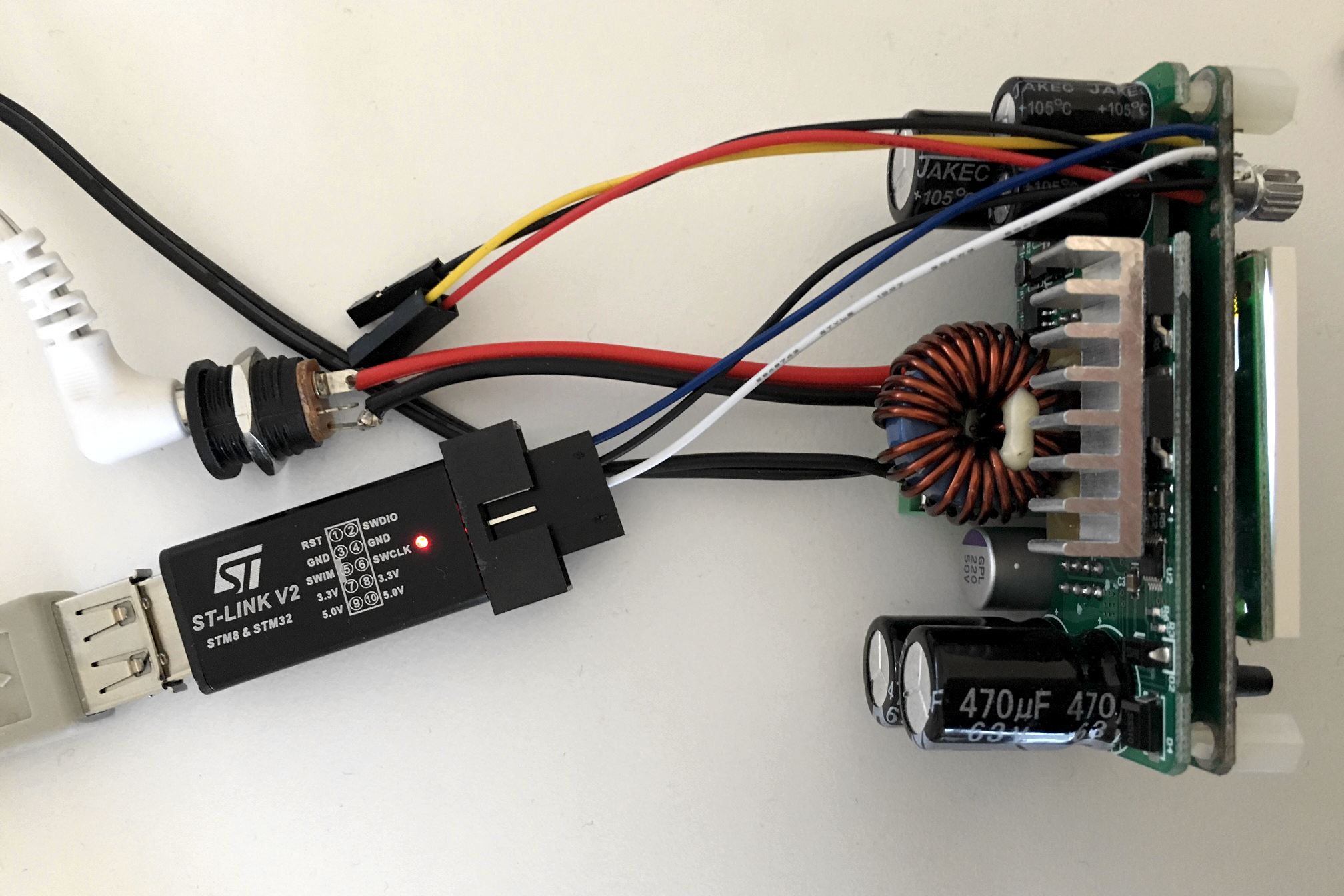
Although this guide is written for the ‘5005 it should work for the entire DPS family but I only have 5005s to test with. Before we begin I should mention that the stock firmware will be gone permanently. As readout protection is enabled on the STM32, the FW cannot be extracted and I have no source for it. Additionally, I take no responsibility if you destroy your DPS. That said, let the fun begin. You will need a DPS5005 (or similar), an STLink clone and some wire. Either you solder the wire onto the DPS or you can use female-male dupont wires for flashing.
Teardown
First you need to remove the PCB from the (semi) housing. Use a small flat screwdriver to prey the PCB loose from the retaining flaps.
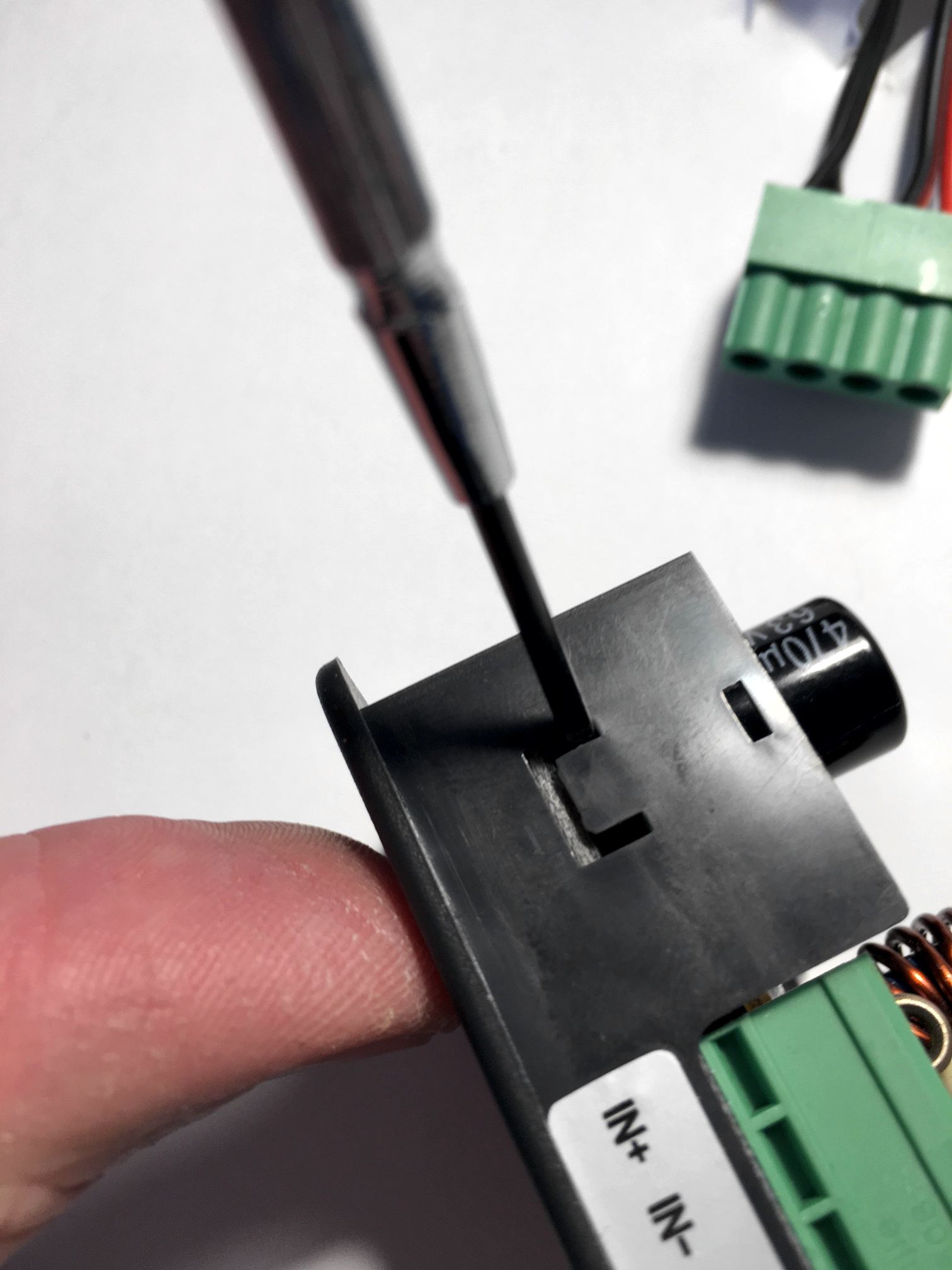
Be careful not to break the retaining flaps (not that they’re fragile, but still). They are very much needed for holding the front panel in place when you press the buttons.
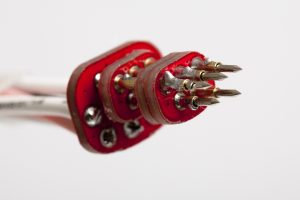
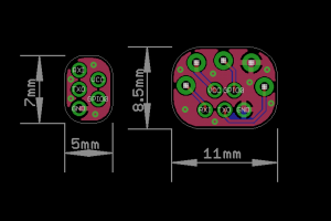
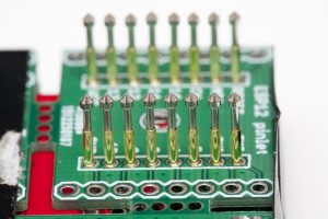
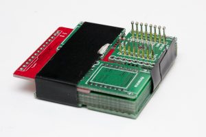
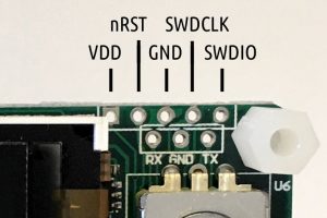
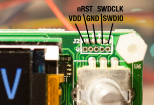
If you have an older version (below left) you can solder some AWG26 wire onto the SWO and UART ports. It is advisable not to solder pin headers as there is limited room inside the housing. I added dupont jumper housings at the end of the cables to aid in connecting them to the STLink clone and FTDI ditto. Hint: make the cables “stretch” backwards, from the display. For newer versions (below right) the 1.25mm JST-GH there is little room for the SWD wires. As a bonus, you need not solder the UART cables in case you bought one of the “communications versions”.
If you do not want to solder (and do not want any remote control) (and have steady hands) you could connect three female-male dupont cables to the STLink clone and hold them pressed against the DPS while flashing.
Building OpenDPS
With that in place you should install OpenOCD and an ARM GCC toolchain. For GCC, Launchpad is a good place to start. For OpenOCD, YMMW. If you are on macOS you can find OpenOCD here (it installs as /Applications/GNU ARM Eclipse/OpenOCD/0.10.0-201610281609-dev/bin/openocd). With the tools in place you’re ready for the next step.
git clone --recursive https://github.com/kanflo/opendps.git
cd opendps
make -C libopencm3
make -C opendps
make -C dpsboot
Flashing
Next you need to unlock the internal flash of the STM32 before flashing (which causes a complete erase). Start OpenOCD:
cd openocd/scripts
openocd -f interface/stlink-v2.cfg -f target/stm32f1x.cfg
You will receive a few lines of output ending with “Info : stm32f1x.cpu: hardware has 6 breakpoints, 4 watchpoints” if the connection was successful.
Please note! Before you unlock and erase the STM32 flash, you should make a dump of the STM32 peripheral settings of your stock DPS firmware. The DPS hardware might change at any time and if you flash OpenDPS and it does not work because eg. the GPIO pin enabling output power was changed, things get difficult. The ocd-client.py script will assist you now that OpenOCD is running. Please note that OpenOCD might interfere with the stock firmware. When you connect, the stock FW might lock up. First, power on the DPS and make sure the power output is disabled but set to e.g. 5V, start OpenOCD and type:
./ocd-client,py all > 5V-off.txt
If needed, restart the unit (and OpenOCD), enable power output @ 5V and type:
./ocd-client,py all > 5V-on.txt
Rinse and repeat for one or two more voltage levels. Check the log files, there should be no lines saying “Parsing error”. If your OpenDPS does not work, these files will enable me (or someone else, remember this is open source you 😀 ) to pinpoint the problem. Additionally, you should test the device before unlocking it. Enable power, connect something and verify that your unit actually works.
Now let’s wipe that flash. In another terminal:
telnet localhost 4444
and type:
reset halt
flash erase_address unlock 0x08000000 0x10000
You will probably get the following, ending with an error:
Device Security Bit Set
stm32f1x.cpu: target state: halted
target halted due to breakpoint, current mode: Thread
xPSR: 0x61000000 pc: 0x2000003a msp: 0x20000800
stm32x device protected
failed erasing sectors 0 to 63
Keep calm. Restart OpenOCD, toggle power on the DPS and try again. This time you should see:
erased address 0x08000000 (length 65536) in 0.094533s (677.012 KiB/s)
Time to flash (flash the app first, then the boot loader):
make -C opendps flash
make -C dpsboot flash
The last two lines should read:
** Verified OK **
** Resetting Target **
and your DPS5005 is now an OpenDPS 5005.
Congratulations! If things went south somwhere, feel free to ask for help in the comments below.
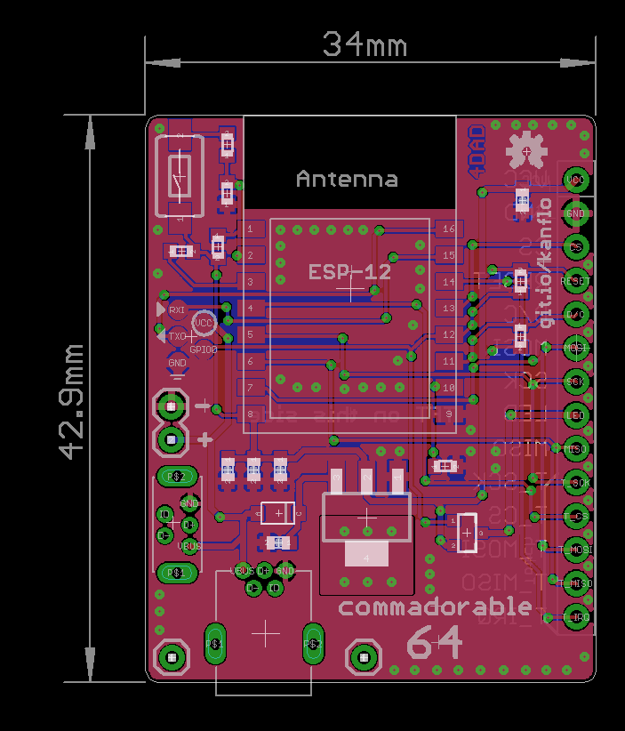
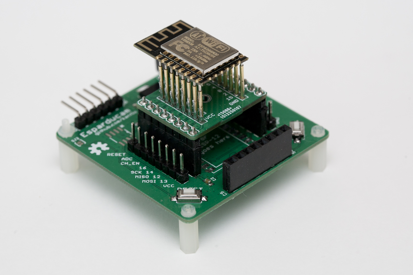
From here you can use the OpenDPS as a stand alone device, control it via a serial port or control it via wifi by connecting an ESP8266.
Short User Manual
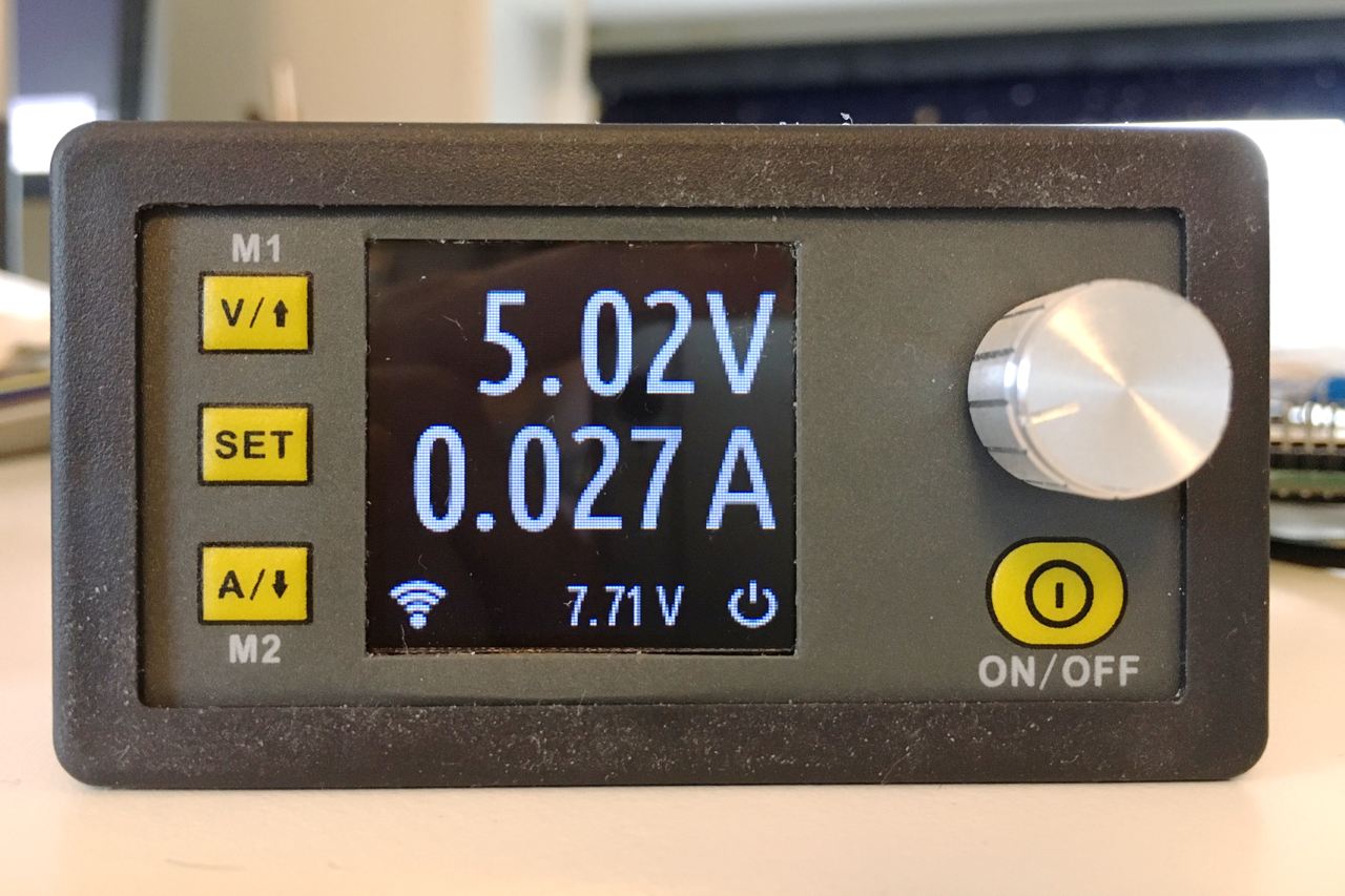
When you power on your OpenDPS, the current voltage and current limit settings are displayed and the power output is always disabled. Pressing ON/OFF will enable power output and the display will now show the measured output voltage and the measured current draw. If the screen flashes once and goes back to displaying the voltage/current settings, the over current protection kicked in. Press ON/OFF again to disable the power output.
Press the SET button to go into editing mode. Press the V and A buttons to move between the voltage and current settings. Press the rotary knob to step sideways and turn the knob to change the values. Press SET again to exit editing mode.
Press and hold the knob for two seconds to lock the keys, long press again to unlock. A long press of the SET key will invert the display.
When your OpenDPS starts it will wait for a wifi connection from a connected ESP8266 and the wifi icon will flash at 1Hz. If it does not get a wifi connection, the wifi icon will be turned off after 10 seconds. If there was an error connecting to your wifi network, the wifi icon will flash at 4Hz.
Remote Serial Control
If you soldered wires to the UART port, connect an FTDI adapter and try the dpsctl.py tool:
dpsctl.py -d /dev/tty.usb.yourdevice --ping
The TFT should flash once as a visual indication. If you get ‘Error: timeout talking to device’, check if you swapped RX and TX and/or forgot to connect GND.
The port setting can be set in an environment variable
export DPSIF=/dev/tty.usb.yourdevice
After setting the DPSIF variable, you can try setting the output voltage to 3.3V:
dpsctl.py --voltage 3300
enable the output:
dpsctl.py --power on
check the measurements:
% dpsctl.py --status
V_in : 7.71 V
V_set : 3.30 V
V_out : 3.32 V (on)
I_lim : 0.100 A
I_out : 0.040 A
% make -C opendps bin
% dpsctl.py -d /dev/ttyUSB0 -U opendps/opendps.bin
make clean ; make WIFI=0 flash
Remote Wifi Control
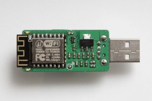
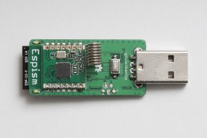
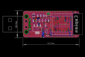
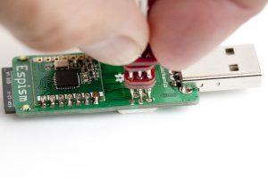
For wifi control, any good old ESP8266 board with the UART exposed will work. Connect GND, RX and TX, build and flash esp8266-proxy (don’t forget to set your wifi credentials) and you should be good to go.
git clone --recursive https://github.com/superhouse/esp-open-rtos.git
export EOR_ROOT=`pwd`/esp-open-rtos
echo '#define WIFI_SSID "my ssid"' > esp-open-rtos/include/private_ssid_config.h
echo '#define WIFI_PASS "my secret password"' >> esp-open-rtos/include/private_ssid_config.h
cd /path/to/esp8266-proxy
make && make flash
Note that you currently cannot use the master branch on the main ESP Open RTOS repository as my PR for a function needed for multicast has not been merged yet.
When your OpenDPS has connected to your wifi network, try the ‘scan’ command to find out its IP number:
% dpsctl.py --scan
172.16.3.203
1 OpenDPS device found
Next try pinging it:
% dpsctl.py -d 172.16.3.203 --ping
The TFT should flash once as a visual indication. If you get ‘Error: timeout talking to device 172.16.3.203’, check if you swapped RX and TX. The dpsctl.py tool has the same functionality over wifi as well as the serial port.
Sadly, you cannot power your ESP8266 from your OpenDPS. The VDD pin next to the SWO port is connected to U4 (under the TFT), an MD7133H 3.3V regulator which only provides a measly 30mA (yes, thirty). Additionally, this regulator is powered by U3 (on the backside, next to the screw terminal) which is an XL7005A supplying 400mA @ 5V which could be a bit over the edge for a power hungry, cold booting ESP8266.
Todos
There are a few todos in the code but overall OpenDPS should be stable for everyday use.
That’s it, have fun hacking your DPS5005!